
Polishing apparatus and method

a technology of polishing apparatus and polishing efficiency, which is applied in the direction of lapping machines, manufacturing tools, and abrasive surface conditioning devices, etc., can solve the problems of lowering the polishing efficiency, affecting the polishing speed, and affecting the polishing efficiency

Inactive Publication Date: 2000-07-25
NEC CORP
View PDF7 Cites 46 Cited by
  • Summary
  • Abstract
  • Description
  • Claims
  • Application Information

AI Technical Summary

Benefits of technology

Accordingly, an object of the present invention is to provide a polishing apparatus and method capable of stably polishing a substrate in spite of the difference in the polishing object and the change in a polishing device with lapse of time.
According to the present invention, information for setting conditioning conditions of a polishing device can be obtained during polishing a substrate so that it is needless to perform a pilot operation for obtaining the conditioning conditions in the interval of the runs. Further, even when properties of a substrate (for example, device pattern and kind of film) are partially different, local (partial) information corresponding to the partial properties can be obtained during polishing the substrate so that it is easy to set optimum conditioning conditions which are locally different part by part according to the information.

Problems solved by technology

Namely, the following problems are involved in the aforementioned prior art.
The first problem is to perform a pilot operation on the same conditioning condition in the next operation, i.e., without changing conditioning conditions in one and next pilot operations.
As a result, a polishing speed varies at every run performed in one and next pilot operations due to disorder such as the change of a polishing pad in its surface state, variation between lots, ununiformity of an abrasive agent and the like.
Consequently, it is in fear of polishing a wafer excessively.
The second problem is to require the determination of conditioning conditions (or make of a recipe) for every different part in properties by correspondingly performing the pilot operations according to the conventional method of setting conditioning conditions, since the degree of lowering a polishing efficiency due to the fatigue of a polishing pad, clogging and the like changes depending on the kind of polishing object (kind of film and the like) and the device pattern formed on a wafer.

Method used


Image

  • Polishing apparatus and method
  • Polishing apparatus and method
  • Polishing apparatus and method

Examples


example 1

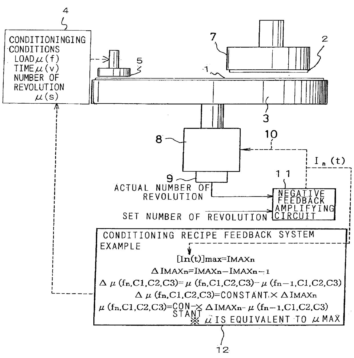
FIG. 1 is an explanatory view of a polishing apparatus of Example 1. As illustrated in FIG. 1, a polishing table 3 with a polishing pad 1 adhered thereto is rotated by a table motor 8. The number of revolution of the polishing table can be detected by an encoder 9 attached to the table motor 8. A signal corresponding to the detected number of revolution (signal corresponding to an actual number of revolution) output by the encoder 9 is input into one input terminal of a negative feedback amplifying circuit 11. Set number of revolution of the polishing table 3 is input into another reference input terminal of the negative feedback amplifying circuit. By the negative feedback amplifying circuit the actual number of revolution of the polishing table is compared with the set number of revolution and a torque current to be supplied to the table motor 8 is controlled so as to make the actual number of revolution approximate or equal to the set number of revolution.

A wafer 2 is held by a s...

example 2

In Example 2 the relation of number of revolution of the polishing table during conditioning and wafer polishing speed in a run after conditioning was investigated under the condition that the number of revolution of the polishing table during polishing is variable and other conditioning conditions are invariable, although the conditioning load was variable in Example 1. Experimental conditions were the same of those in Example 1 except the number of revolution of the polishing table during conditioning. The result of the experiment is shown in FIG. 11.

FIG. 11 indicates that the number of revolution (rotational speed) of the polishing table during conditioning is in approximate proportion to the wafer polishing speed, and accordingly that the wafer polishing speed can be controlled to be constant by changing the number of revolution of the polishing table during conditioning.

example 3

In this Example 3, total polished amount is controlled to be constant mutually throughout runs by controlling the sum (integrated value) of torque currents during run, although the maximum value of the torque current was controlled to beconstant in different runs from each other in Examples 1 and 2. Details of Example 3 will be explained as follows.

The following formula is derived from the above formulae (1), (2) and (7).

Total polished amount during a period of polishing=.intg.I(t)dt=constant.times..intg.fsvd.times.r(t)dt(12)

The formula (12) indicates that the total polished amount during the period is a function of ".intg.fsvd", and accordingly that the sum of the torque currents during the period, or the total polished amount can be controlled by changing conditioning conditions (f, s, v, d). The method of setting conditioning conditions disclosed in Example 3 can be also applied, for example, in the case that the change of the torque current during polishing does not exhibit line...


PUM


Abstract

A polishing apparatus and method capable of polishing stably irrelevant of disorder such as the change of a polishing object, change of a polishing device with lapse of time. A polishing apparatus includes polishing pad 1, polishing table 3 with the polishing pad adhered thereto, table motor 8 for driving the polishing table 3, conditioning device 5 of the polishing pad 1 and conditioning control system 12 for setting conditioning conditions. According to a polishing method of the present invention, conditioning conditions of the polishing pad 1 are set on based on a frictional force exerted between the polishing pad 1 and a substrate or on torque current 10.

Description

The present invention relates to polishing apparatus and method, more especially to polishing apparatus and method for polishing a substrate.FIGS. 12 (A) and 12 (B) show a conventional polishing apparatus for polishing a wafer (substrate). Referring to FIGS. 12 (A) and 12 (B), according to the conventional polishing apparatus, a wafer 2 is polished through the steps of dropping a droplet of a slurry, which contains an abrasive agent and which is fed from a slurry feed means 6, on a polishing pad 1 adhered to a rotatable polishing table 3, pressing the wafer 2 rotated by a spindle 7 against the polishing pad. In order to remove debris and the like which clog traps (grooves) formed on the surface of the polishing pad 1, conditioning of a polishing pad (called as to "Ex-SITU conditioning") is performed by using a diamond disc 5 installed on a conditioning drive means 4 during the interval between polishing steps (runs).Conventionally, conditioning conditions have been determined by pra...

Claims


Application Information

Patent Timeline
IPC IPC(8): B24B49/16B24B37/04B24B53/007B24B27/00B24B53/017H01L21/304
CPCB24B49/16B24B53/017
Inventor INABA, SHOICHIKATSUYAMA, TAKAOTANAKA, MORIMITSU
Owner NEC CORP
Features
  • Generate Ideas
  • Intellectual Property
  • Life Sciences
  • Materials
  • Tech Scout
  • Unparalleled Data Quality
  • Higher Quality Content
  • 60% Fewer Hallucinations
Learn More