Data transmission

a data transmission and data technology, applied in the field of data transmission, can solve problems such as signal distortion due to distortion

Inactive Publication Date: 2000-07-25
BRITISH TELECOMM PLC
View PDF14 Cites 57 Cited by
  • Summary
  • Abstract
  • Description
  • Claims
  • Application Information

AI Technical Summary

Problems solved by technology

In practice, in a multi-level system there are distortions in the sig

Method used


Image

  • Data transmission
  • Data transmission
  • Data transmission

Examples


Embodiment Construction

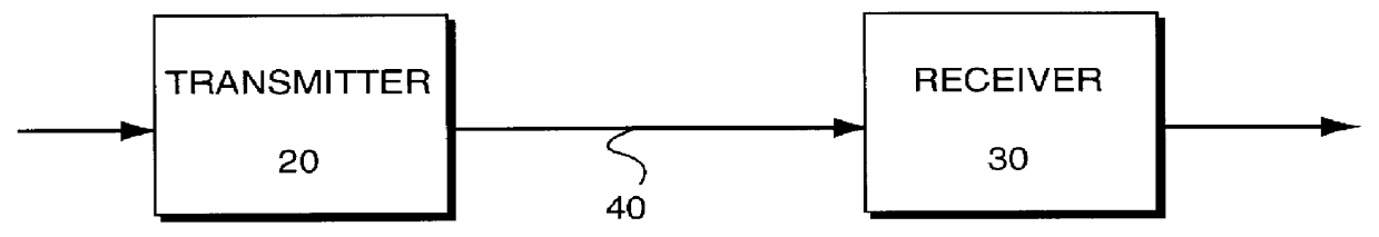
As shown in FIG. 1 the digital data transmission system comprises a transmitter 20, a receiver 30 and a communications link 40. Data is transmitted from the transmitter 20 to the receiver 30 via the communications link 40 which may take any suitable form. For example the communications link 40 may be part of a Public Switched Telephone Network (PSTN), a dedicated line such as provided by an Integrated Services Digital Network (ISDN), a radio link, coaxial cable, optical fibre etc.

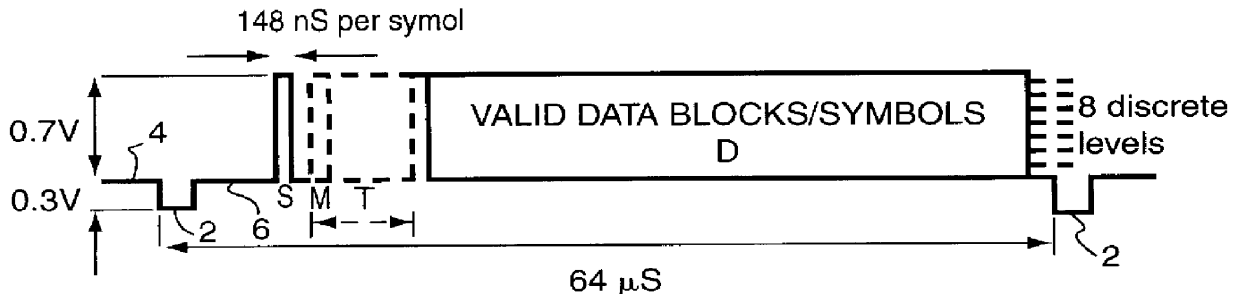
For illustrative purposes, the data transmission system to be described refers to the transmission of data representing a video image. However the invention is applicable to any system that transmits multi-level digital data, in particular for transmission over an analogue transmission link e.g. cable modems, higher bit rate teletext services.

The data transmission system to be described is suitable for distributing digital television signals to customers over an analogue hybrid fibre-coax network. In order ...


PUM


Abstract

A transmitter (20) having means (206, 207) to encode an input signal to form coded data, each element of said coded data having one of at least two discrete signal magnitude levels, the encoding means including in the coded data a periodic training sequence of data (T); and a receiver (30) to receive the coded data and, on the basis of the received training sequence, to adapt a threshold or thresholds to allow the discrete levels to be distinguishable from each other. The training sequence T may comprise a plurality of elements at least one of which, in turn, represents each one of the discrete signal levels. The receiver generates a look-up-table to store the adapted thresholds.

Description

1. Field of the InventionThis invention relates to data transmission and in particular to data transmission in which a multi-level representation of a digital signal is transmitted.2. Related ArtDigital data represents a signal that has been quantized in both time and amplitude. The digital data thus approximates the actual value of an analogue signal. If an analogue signal is digitized, the range of the analogue signal is divided into a number of levels e.g. 16, the analogue signal is sampled at set intervals and the appropriate level at that instant is determined. Since only 16 levels are used, the level which is closest to the actual level is chosen. A signal that is reconstructed from this digital data resembles but is not exactly the same as the original analogue signal.In binary digital data, a signal is represented by 0 or 1, a 0 being a 0 V pulse and a 1 being a 5 V pulse for example. If a sample of an input signal has an amplitude greater than half of the maximum range, the...

Claims


Application Information

Patent Timeline
IPC IPC(8): H04L1/00H04L25/06
CPCH04L1/0045H04L1/0057H04L25/063
Inventor HERON, ANDREW PETER
Owner BRITISH TELECOMM PLC
Why Eureka
Try Eureka