

Electromagnetic safety enhancement circuit for universal serial bus systems
- Summary
- Abstract
- Description
- Claims
- Application Information
AI Technical Summary
Problems solved by technology
Method used
Image

Examples
first preferred embodiment
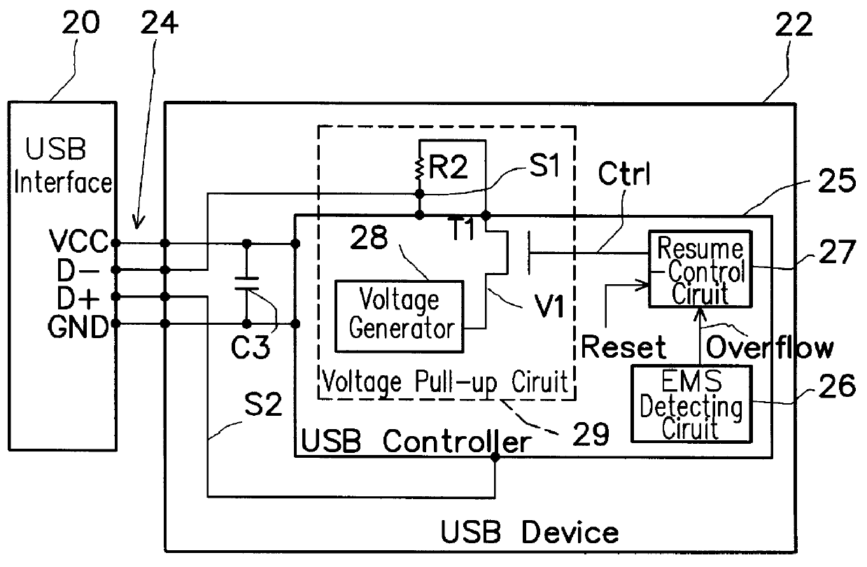
FIG. 2 is a schematic block diagram of a USB system utilizing the first preferred embodiment of the EMS enhancement circuit according to the invention.
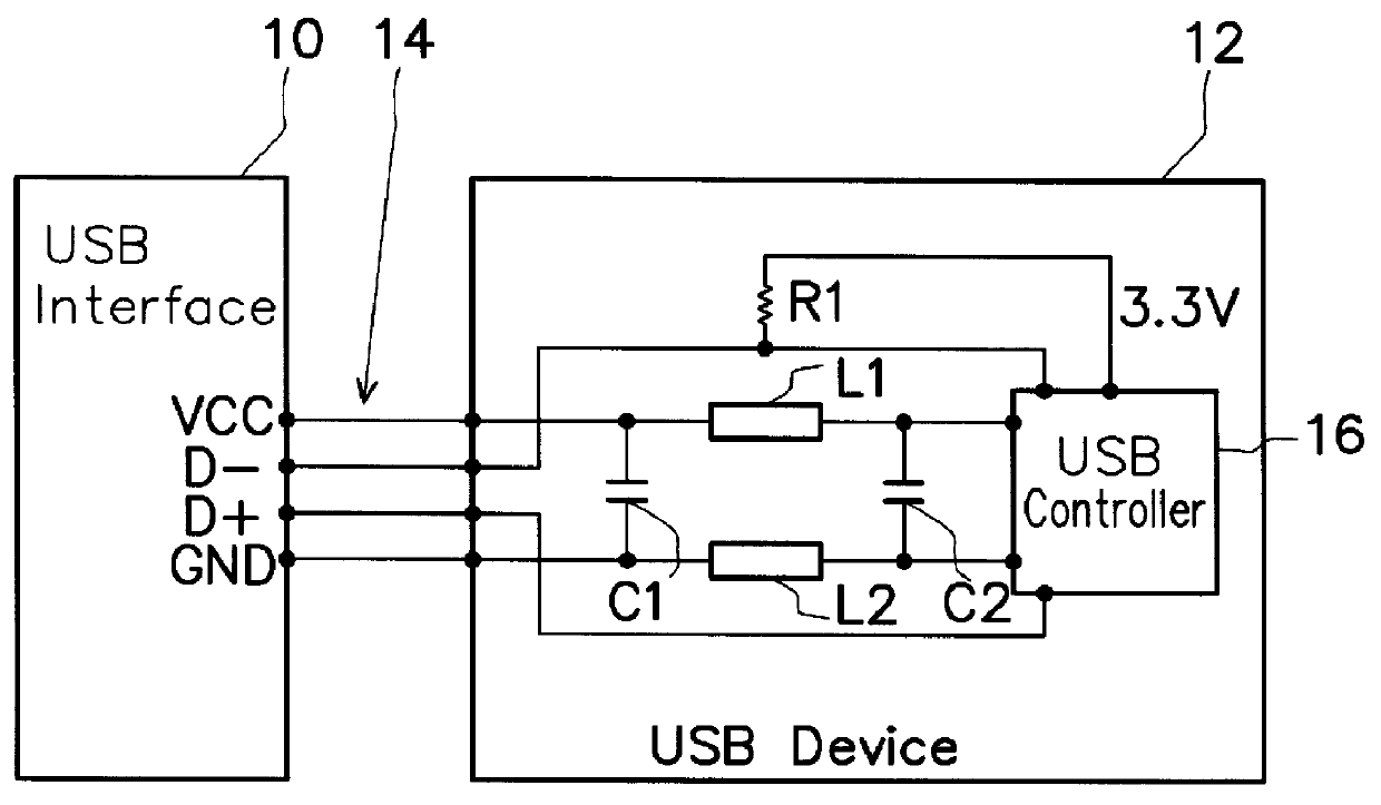
As shown, the USB system includes a USB interface 20 and a USB device 22 connected via a cable 24 to the USB interface 20. By specification, the USB interface 20 is provided with a power line V.sub.CC, a data line D+, a complementary data line D-, and a ground line GND. These lines are entirely identical in functionality as those depicted in the prior art of FIG. 1, so detailed description thereof will not be repeated. It is a characteristic feature of the invention that, with the USB system being provided with the EMS enhancement circuit of the invention, the cable 24 can be a single-shield structured cable rather than the high-cost double shield structured cable used in the prior art of FIG. 1. The reason for this will be given later in this section.
The USB device 22 includes a USB controller 25 which is provided in accordance with ...
second preferred embodiment
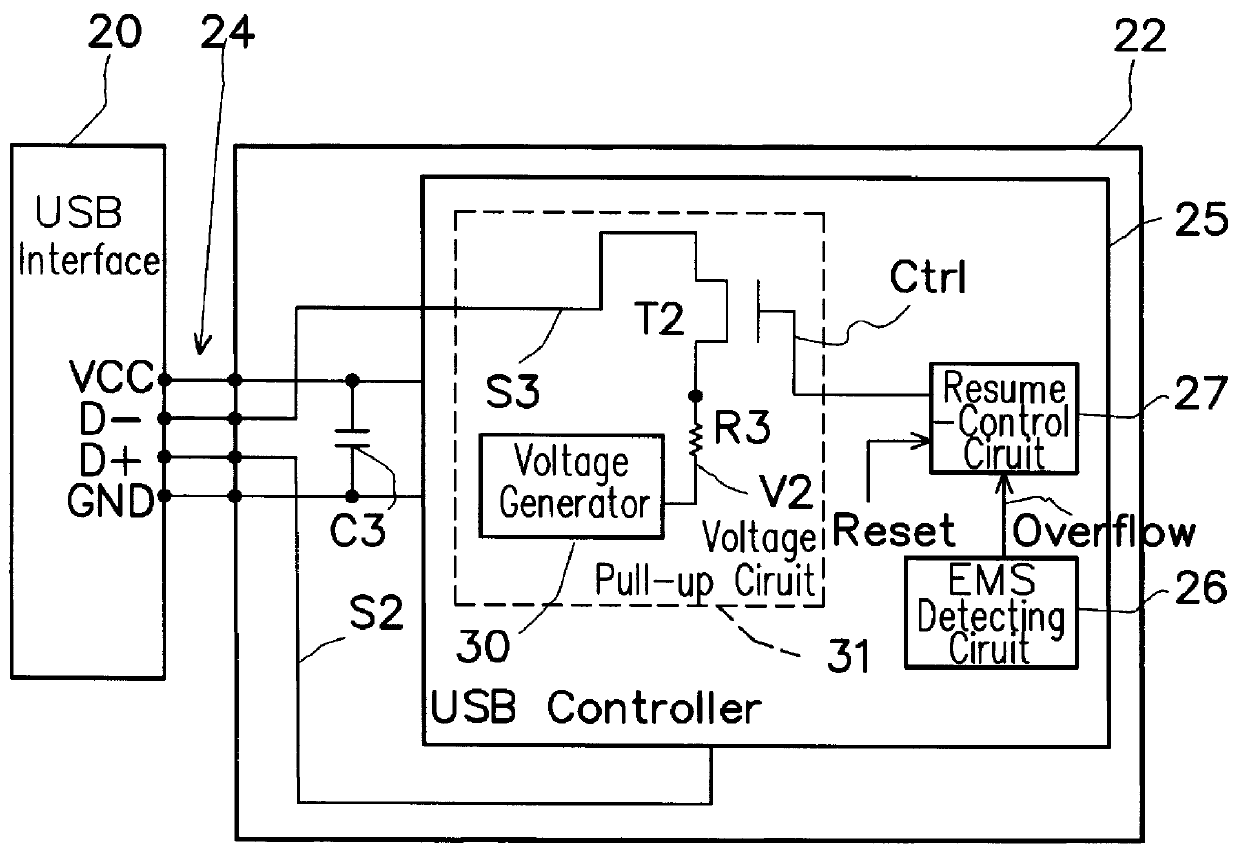
FIG. 3 is a schematic block diagram of a USB system utilizing the second preferred embodiment of the EMS enhancement circuit according to the invention. This embodiment differs from the previous one day only in that the voltage pull-up circuit, here designated by the reference numeral 31, is different in inside structure from the voltage pull-up circuit 29 shown in FIG. 2. Beside this, all the other constituent elements are identical to those used in the first embodiment of FIG. 2 and are thus labeled with the same reference numerals.
As shown, the voltage pull-up circuit 31 used here is composed of a voltage source 30 for generating an output voltage V2; a resistor R3 connected in series to the output of the voltage source 30; and a switching device, such as a transistor T2, whose ON / OFF state is controlled by the pull-up control signal Ctrl from the resume-control unit 27, and which has an input end connected to the resistor R3 and an output end connected directly to the complement...
PUM
 Abstract
Description
Claims
Application Information