Fuel injection system

a technology of fuel injection system and fuel distribution line, which is applied in the direction of liquid fuel feeders, machines/engines, mechanical equipment, etc., can solve the problems of difficult installation of fuel distribution line, slight tilt of fuel injection valve in the location hole, and even more difficult assembly of fuel distribution lin

Inactive Publication Date: 2000-08-15
ROBERT BOSCH GMBH
View PDF12 Cites 40 Cited by
  • Summary
  • Abstract
  • Description
  • Claims
  • Application Information

AI Technical Summary

Problems solved by technology

However, the resulting rigid attachment of the fuel injection valves to the cylinder head makes the installation of the fuel distribution line difficult, since positional and angular deviations may occur between the inlet sections of the fuel injection valves and the location elements of the distribution line.
Another contributing factor is that the fuel injection valves installed in the location holes of the cylinder head are not exposed to the hold-down force of the bracket in a uniform manner around their peripheries, but point-wise, which results in a slight tilt of the fuel injection valves in the location holes.
The additional positional and angular deviations thus resulting at the inlet sections of the fuel injection valves make the assembly of the fuel distribution line even more difficult.
In addition to the more difficult assembly, a fuel leakage danger at the seal that does not compensate for the positional and angular deviations also results in practice with Japanese Patent No. 08 312503.

Method used


Image

  • Fuel injection system
  • Fuel injection system

Examples


Embodiment Construction

.

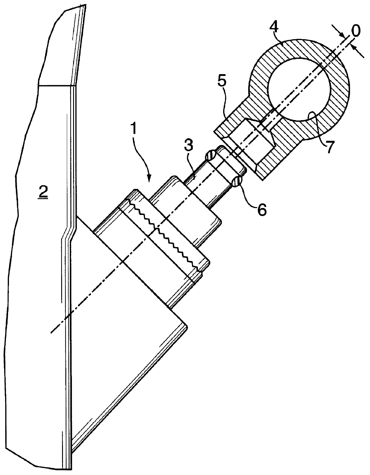
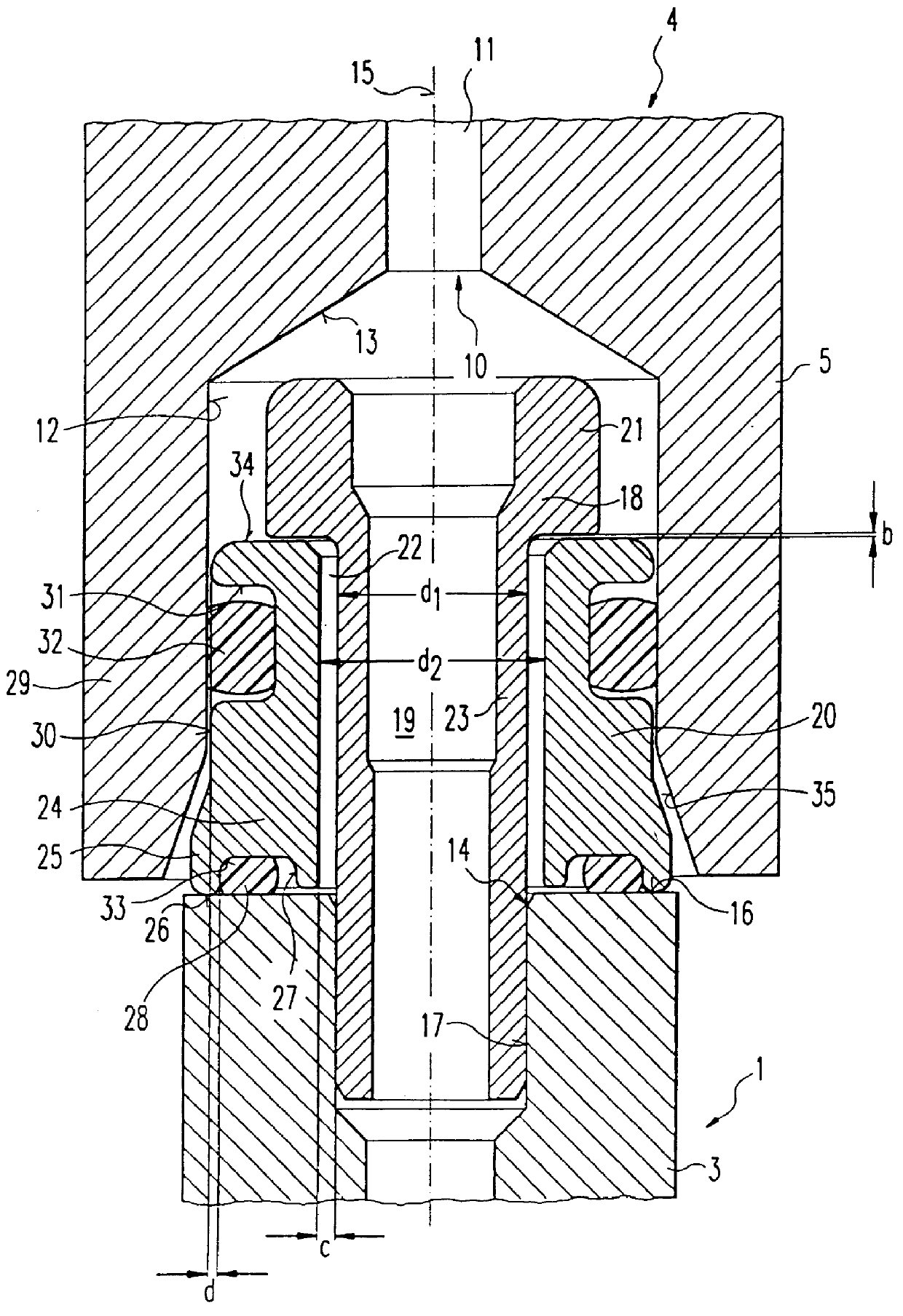
Prior to describing in detail the embodiment of the present invention illustrated in FIG. 2, we shall briefly describe, with reference to FIG. 1, the conventional assembly of fuel injection valve 1 on cylinder head 2 of the internal combustion engine (not illustrated in detail) and the connection of inlet section 3 of fuel injection valve 1 with the fuel distribution line 4 illustrated as a section in FIG. 1.

Fuel injection valve 1 is installed in a relatively rigid manner on cylinder head 2 by inserting it in a cylinder head hole not illustrated in FIG. 1. Usually one fuel injection valve 1 is provided for each combustion chamber of the internal combustion engine. After inserting fuel injection valve 1 into the respective cylinder hole in cylinder head 2, fuel distribution line 4 is installed for supplying fuel from a fuel pump (not illustrated) to the individual fuel injection valve 1. Inlet section 3 of each fuel injection valve 1 is inserted in a respective fitting 5 of fuel dis...


PUM


Abstract

PCT No. PCT/DE98/00810 Sec. 371 Date Feb. 10, 1999 Sec. 102(e) Date Feb. 10, 1999 PCT Filed Mar. 19, 1998 PCT Pub. No. WO98/58169 PCT Pub. Date Dec. 23, 1998A fuel injection system for injecting fuel into an internal combustion engine having at least one fuel injection valve, which has a fuel inlet orifice on an inlet section and having a fuel distribution line, which has, for each fuel injection valve a fuel outlet orifice that may be connected to the fuel inlet orifice of the fuel injection valve, and a connection fitting, connected downstream to the fuel outlet orifice. A connection arrangement injection valve to the respective fuel outlet orifice of the fuel distribution line is provided. The connection arrangement includes an annular seal support and a sleeve that can be inserted in the fuel inlet orifice. The annular seal support has a first sealing element for sealing the seal support against the inlet section of the fuel injection valve, and a second sealing element for sealing the seal support against the connection fitting of the fuel distribution line.

Description

The present invention relates to a fuel injection system for injecting fuel into an internal combustion engine, in particular for direct injection of fuel into the combustion chamber(s) of the internal combustion engine.BACKGROUND INFORMATIONJapanese Patent No. 08 312503 describes that location holes may be provided on the cylinder head of an internal combustion engine for one fuel injection valve for each combustion chamber in each hole, where an outlet section of the respective fuel injection valve for direct injection of fuel in the respective combustion chamber can be inserted. The fuel injection valve inserted in the location hole of the cylinder head is held down using a holding device designed as a bracket against the relatively high combustion pressure prevailing in the combustion chamber. In order to reliably secure the fuel injection valves in the location holes, relatively high hold-down forces must be exerted by the brackets on the fuel injection valves, so that the fuel...

Claims


Application Information

Patent Timeline
Patent Type & Authority Patents(United States)
IPC IPC(8): F02M55/00F02M69/46F02M55/02F02M61/16
CPCF02M55/004F02M69/462F02M69/465F02M69/46
Inventor FURST, THOMAS
Owner ROBERT BOSCH GMBH
Why Eureka
Try Eureka