A pleural manometry catheter

a manometer and pleural fluid technology, applied in the direction of catheters, diagnostic recording/measuring, applications, etc., can solve the problems of not being able to use a manometer to measure the pleural fluid pressure, the operation cannot be dynamically monitored, and the duration of the operation is rather long, so as to reduce the duration of the operation and be used more quickly

Active Publication Date: 2016-09-15
ROCKET MEDICAL
View PDF14 Cites 1 Cited by
  • Summary
  • Abstract
  • Description
  • Claims
  • Application Information

AI Technical Summary

Benefits of technology

[0019]A further, unexpected and very marked advantage of the device of the invention is that there is no need for a priming step in order to use the manometer of the invention, the operator can zero the unit before catheter insertion, insert the catheter and then measure the pressure in the pleural space immediately without having to go through a separate priming procedure.
[0020]This primary advantage has a number of advantageous effects. First and foremost, pleural manometry catheter can start to be used more quickly without the priming step. Starting more quickly may lead to the reduction of the duration of the operation overall is Second there is no need to undertake, or even know how to undertake, a separate priming procedure. As such, a wider cross-section of users may operate the device, and this can be particularly important in an emergency context, wherein the catheter must be inserted and used quickly and in other instances staff knowledgeable of the priming step may not be available.
[0021]Third, removal of the calibration step leads to lighter, more portable and smaller apparatus—a more usable pleural manometry catheter.

Problems solved by technology

Disadvantageously, this is not a real-time system and as such the dynamic measuring of lung pressure cannot be undertaken.
In any context, but particularly in an emergency context, where lung pressure is likely to change swiftly, such start-stop measurement is sub-optimal, as well as being an unwieldy and therefore impracticable procedure.
Further, prior to the aspiration of the first quantity of fluid, the manometer cannot be used to measure the pleural fluid pressure.
Further, the assembly of apparatus comprises several parts which must be assembled before the procedure takes place, and this can be unwieldy.
The prior art devices share the disadvantage that they all take rather a long time to use—in particular, they all require a calibration step to be undertaken, which is time consuming and requires a certain amount of prior knowledge in order to be effected.
It is possible to envisage a situation in which the user does not know how to prime a prior art manometer and as such produces data which is inaccurate, leading to mistreatment of the patient.

Method used


Image

  • A pleural manometry catheter
  • A pleural manometry catheter
  • A pleural manometry catheter

Examples


Embodiment Construction

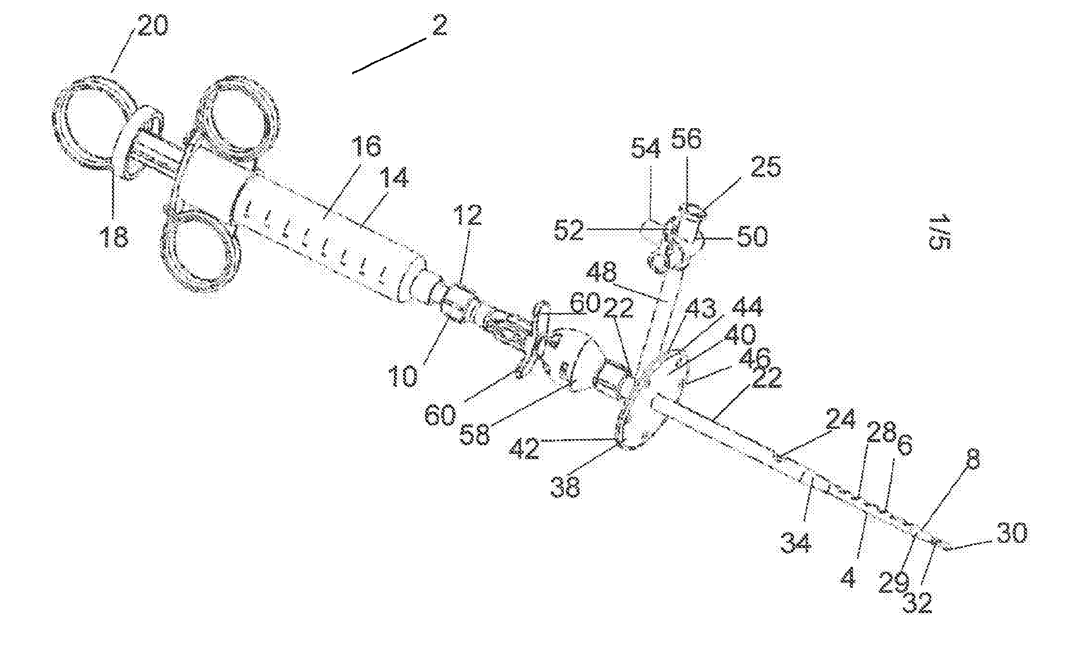
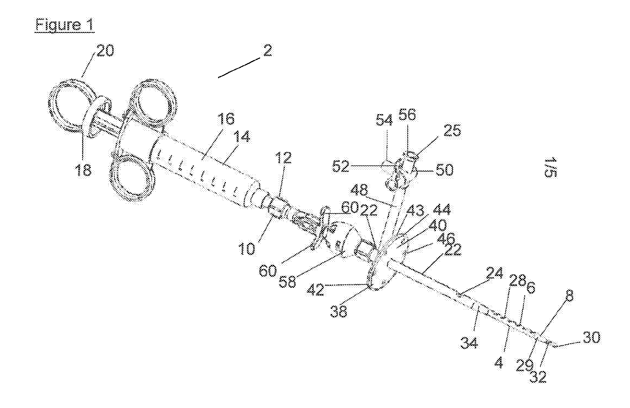
[0059]At FIG. 1, there is shown a pleural manometry catheter, indicated generally at 2. The catheter 2 comprises a first tube 4 comprising a first flow path running from the apertures 6 located at the distal end 8 of the catheter 2, to attachment 10, which in preferred embodiments is a luer connector, at the proximal end 12 of the catheter 2; the attachment 10 allows connection of the catheter 2 to a syringe 14 or other drainage device or system. The catheter 2 may, in some preferred embodiments, comprise an integrated drainage device such as an integrated syringe. Here the syringe 14 is not integrated, being of conventional construction and comprising a barrel 16 and a plunger 18 attached to a handle 20, the syringe being so arranged that when the plunger 18 is pulled via the handle 20, negative pressure is asserted such that fluid may be pulled along the first tube 4 into the barrel 16 of the syringe 14. The catheter 2 is presented to the practitioner as a single integrated unit, ...


PUM


Abstract

A pleural manometry catheter comprises two tubes and a pressure transducer. The first tube provides a first flow path from the pleural cavity to the pressure transducer. The second tube provides a second flow path from the pleural cavity such that fluid can be drained from the pleural cavity. The pressure transducer comprises a processor for processing, continuously, the real-time fluctuations in the pressure of the second flow path and therefore the pleural cavity as fluid is aspirated from it via the first tube.

Description

FIELD OF THE INVENTION[0001]The invention is in the field of a pleural manometry catheter, In particular, the catheter is for use in human patients and for treatment of pleural effusions for diagnostic and therapeutic purposes. The invention is also an apparatus and a device for conducting pleural manometry comprising a pleural manometry catheter. In particular, the device is a pleural manometry catheter for measuring changes in chest cavity pressure in real time.BACKGROUND AND PRIOR ART[0002]Thoracentesis is an invasive procedure to remove fluid or air from the pleural space for either diagnostic or therapeutic purposes; a cannula, hollow needle or catheter, is introduced into the chest and pleural fluid is aspirated through it.[0003]With regard to the diagnostic purposes, pleural fluid can provide information enhancing the practitioner's understanding of the underlying pleural pathophysiology when an effusion is present, thereby allowing the source and / or cause of the pleural effu...

Claims


Application Information

Patent Timeline
Patent Type & Authority Applications(United States)
IPC IPC(8): A61M1/00A61M39/22A61M25/00A61B5/03A61B5/00
CPCA61M1/008A61B5/036A61B5/746A61M2205/18A61M39/22A61M2205/3344A61M2210/101A61M25/003A61B5/4836A61M2025/0039A61M25/00A61M2025/0003A61M2025/0031A61M2025/0037A61M1/73A61M1/84A61B5/03A61M1/00A61M27/00
Inventor ROE, EDWIN RICHARDVAREY, RICHARD MARTIN
Owner ROCKET MEDICAL
Why Eureka
Try Eureka