Anti-leakage apparatus

Inactive Publication Date: 2000-08-15
UNITED MICROELECTRONICS CORP
View PDF4 Cites 1 Cited by
  • Summary
  • Abstract
  • Description
  • Claims
  • Application Information

AI Technical Summary

Problems solved by technology

It can cause a failure of a large number of wafers in processing.
This can cause a failure of a large number of wafers in processing.

Method used


Image

  • Anti-leakage apparatus
  • Anti-leakage apparatus

Examples


Embodiment Construction

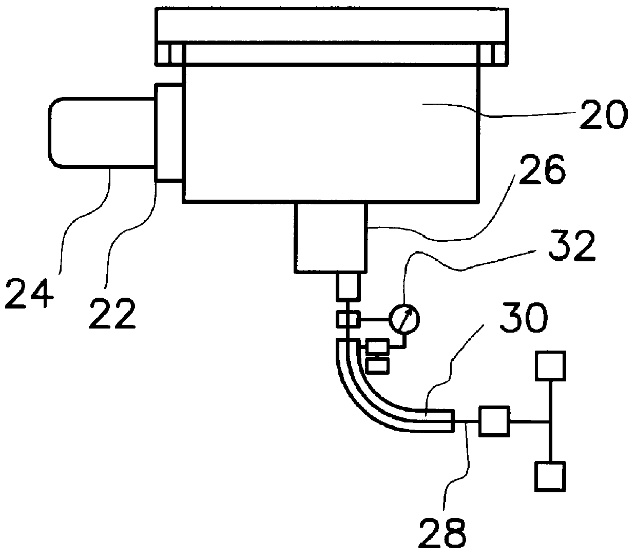
FIG. 2 is a cross-sectional view, schematically illustrating a sputtering deposition equipment including an anti-microleakage apparatus, according to a preferred embodiment of the invention. In FIG. 2, an improved sputtering deposition equipment includes a process chamber 20, a gate valve 22, a cryo-pump 24, a heater 26, an inner bellows line 28, and an anti-microleakage apparatus, which further includes an outer bellows line 30 and a pressure meter 32. The gate valve 22 is coupled to process chamber 20. The cryo-pump 24 is coupled to the gate valve 22. The heater 26 is coupled to the process chamber 20. One end of the inner bellows line 28 is coupled to the heater. The outer bellows line 30 encloses the inner bellows line 28. The pressure meter 32 is coupled to the outer bellows line 30 and reaches to a region between the inner bellows line 28 and the outer bellows line 30.

In a conventional process, since the tolerance of impurity, such as O.sub.2 or H.sub.2 O, is poor during the s...


PUM

PropertyMeasurementUnit
Pressureaaaaaaaaaa
Adhesion strengthaaaaaaaaaa
Metallic bondaaaaaaaaaa

Abstract

An anti-microleakage apparatus is used in a sputtering deposition equipment. A metallic object, such as a wafer, is put in a process chamber. A cryo-pump is used to vacuumed the process chamber. A heater to heat up the process chamber to allow a thermal reaction. The heater is movable and is coupled to an inner bellows line, which allows a low pressure gas can be flushed into the process chamber. The anti-microleakage apparatus is formed on the inner bellows line by wrapping the inner bellows line with an outer bellows line. A higher pressure is created between the inner bellows line and the outer bellow line by filling in a gas. A pressure meter is coupled to the outer bellows line so as to monitor the actual pressure of the higher pressure. When microleakage occurs, the information cab obtained by the pressure meter.

Description

This application claims the priority benefit of Taiwan application serial no. 87113891, filed Aug. 24, 1998, the full disclosure of which is incorporated herein by reference.1. Field of the InventionThis invention relates to an sputtering deposition equipment used in semiconductor fabrication, and more particularly to an anti-microleakage apparatus used in a sputtering deposition equipment in order to prevent microleakage from occurring.2. Description of Related ArtIn semiconductor fabrication, a metal-oxide semiconductor (MOS) structure is usually composed of multiple thin layers, each of which includes different material and thickness. A technology to form these thin layers is so called thin film deposition and thin film growth. The word of deposition means that the formation of the thin layers consumes no material on substrate, which may include only the primary semiconductor substrate or a few more films, such as a silicon oxide layer, already formed.About the deposition technol...

Claims


Application Information

Patent Timeline
IPC IPC(8): C23C14/56H01J37/18H01J37/02
CPCC23C14/564H01J37/18H01J37/32834H01J37/34Y10T137/7722Y10T137/7723Y10T137/7728
Inventor KUO, CHING-I
Owner UNITED MICROELECTRONICS CORP
Why Eureka
Try Eureka