Apparatus and method for a capping machine

a capping machine and apparatus technology, applied in the direction of caps, rotating screw stopper insertion, application, etc., can solve the problems of insufficient thread engagement between the cap and the container, the cap cannot be so tightened that it cannot be opened manually, and the cap or the container or both are damaged

Inactive Publication Date: 2000-08-22
PNEUMATIC SCALE CORP
View PDF11 Cites 75 Cited by
  • Summary
  • Abstract
  • Description
  • Claims
  • Application Information

AI Technical Summary

Benefits of technology

It is a further object of the present invention to use the monitored position and application torque to control further application torque of the screw cap by adjusting the spindle rotational velocity.
It is a further object of the present invention t

Problems solved by technology

However, the cap must not be so tightened that it cannot be opened manually.
Also it must not be so tightened that either the cap or the container or both are damaged.
Too small a number of spindle turns results in insufficient thread engagement between the cap and the container.
This results in insufficient tightness of the cap.
Too large a number of spindle turns results in excessive slipping in the clutch, thereby resulting in less consistent torque control and less efficient cap application.
High speed operation of the capping machine results in high angular velocities of the spindle and the chuck, which may result in over-tightening of the cap.
It may also be difficult to maintain uniformity between the various spindles on a turret.
It is difficult to maintain constant application torque based on the arbi

Method used


Image

  • Apparatus and method for a capping machine
  • Apparatus and method for a capping machine

Examples


Embodiment Construction

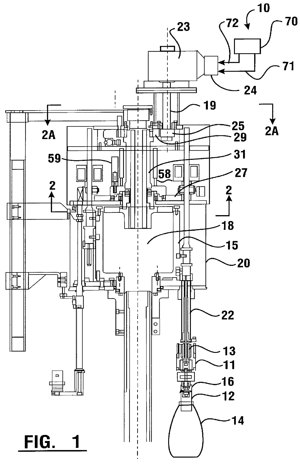
A preferred embodiment of the capping machine 10 of the present invention is shown in FIG. 1. Capping machine 10 has a stationary center shaft 18 around which a turret 20 is rotatably mounted. Turret 20 is rotated by a motor (not shown) whose rotational velocity is adjustable to vary the rate at which containers are processed by the capping machine. A plurality of spindles 22 are supported circumferentially about the turret. A clutch 11 and a cap chuck 16 are positioned at a lower end of each spindle 22.

Spindles 22 are moved upwardly and downwardly parallel to center shaft 18 by a cam 15. In alternative embodiments spindles 22 may be moved upwardly and downwardly parallel to center shaft 18 by a servo motor. Cap chuck 16 may be positioned precisely in a vertical position for containers 14. For subsequent capping operations of containers of a different size, cap chuck 16 may be positioned in the correct vertical position for the capping of that size container.

A threaded cap 12 has th...


PUM


Abstract

A capping machine (10) and method for installing a cap (12) having a threaded portion onto a container (14) having a threaded portion, the threaded portion of the cap corresponding to the threaded portion of the container, the capping machine having a rotatable turret (20) and a rotatable cap chuck (16) which grips the cap and positions the cap on the container. The cap chuck is rotated by a spindle (22) driven by a servo motor (24) at adjustable and reversible rotational velocities independent of the rotational velocity of the turret. The number of rotations of the cap is determined by monitoring the number of rotations of the servo motor compared to the number of rotations of the turret and is transmitted to a spindle drive control(70). The torque imparted to the cap is monitored by a torque monitor (50) and is transmitted to the spindle drive control. The rotational velocity of the cap is adjustable in response to the compared monitored number of rotations and monitored torque. The capped container is released from the cap chuck after a selected number of rotations of the cap onto the container has been made. Caps applied outside a selected range of monitored torques and number of rotations are tracked and rejected.

Description

This invention relates to installing screw caps on threaded containers. More specifically this invention relates to an apparatus and method for installing screw caps on threaded containers using a selected number of cap rotations and simultaneously monitoring a controllable and verifiable application torque.Threaded caps used to seal correspondingly threaded containers are generally known as screw caps. Screw caps for containers are ideally tightened at a predetermined torque. This w torque is selected to close the container sufficiently tightly to avoid loss, deterioration or contamination of the contents during transportation and storage. However, the cap must not be so tightened that it cannot be opened manually. Also it must not be so tightened that either the cap or the container or both are damaged. The position of the threaded cap on the corresponding threads of the container determines when the cap has been properly installed on the container. This position is determined by ...

Claims


Application Information

Patent Timeline
IPC IPC(8): B65B7/28B67B3/20B67B3/00
CPCB65B7/2835B67B3/2033B67B3/208B67B3/264
Inventor GROVE, MICHAEL A.MCSHERRY, SCOTT A.LIEBAL, DAVID W.
Owner PNEUMATIC SCALE CORP
Why Eureka
Try Eureka