Internal combustion engine

Inactive Publication Date: 2000-08-29
ANDREAS STIHL AG & CO KG
View PDF4 Cites 20 Cited by
  • Summary
  • Abstract
  • Description
  • Claims
  • Application Information

AI Technical Summary

Benefits of technology

In both cases the inlet, provided within the interior of the crankcase and connected to the venting line, may be covered by an air-permeable material whereby the fine oil mist that is entrained in the venting air will be separated from the air flow within the material of the fabric, non-woven etc. in the form of small droplets and is then mechanically precipitated by centrifugal forces resulting from the rotation of the component and returned into the crankcase. For increasing the separation effect, the venting line can have a widened portion, i.e., a portion having a larger diameter, which can be embodied as a cone. Expediently, within the cone a rebound plate or a truncated cone structure, widening in the direction of the venting line, may be positioned, b

Problems solved by technology

Accordingly, complicated separating devices must be provide

Method used


Image

  • Internal combustion engine
  • Internal combustion engine
  • Internal combustion engine

Examples


Embodiment Construction

The present invention will now be described in detail with the aid of several specific embodiments utilizing FIG. 1 through 14.

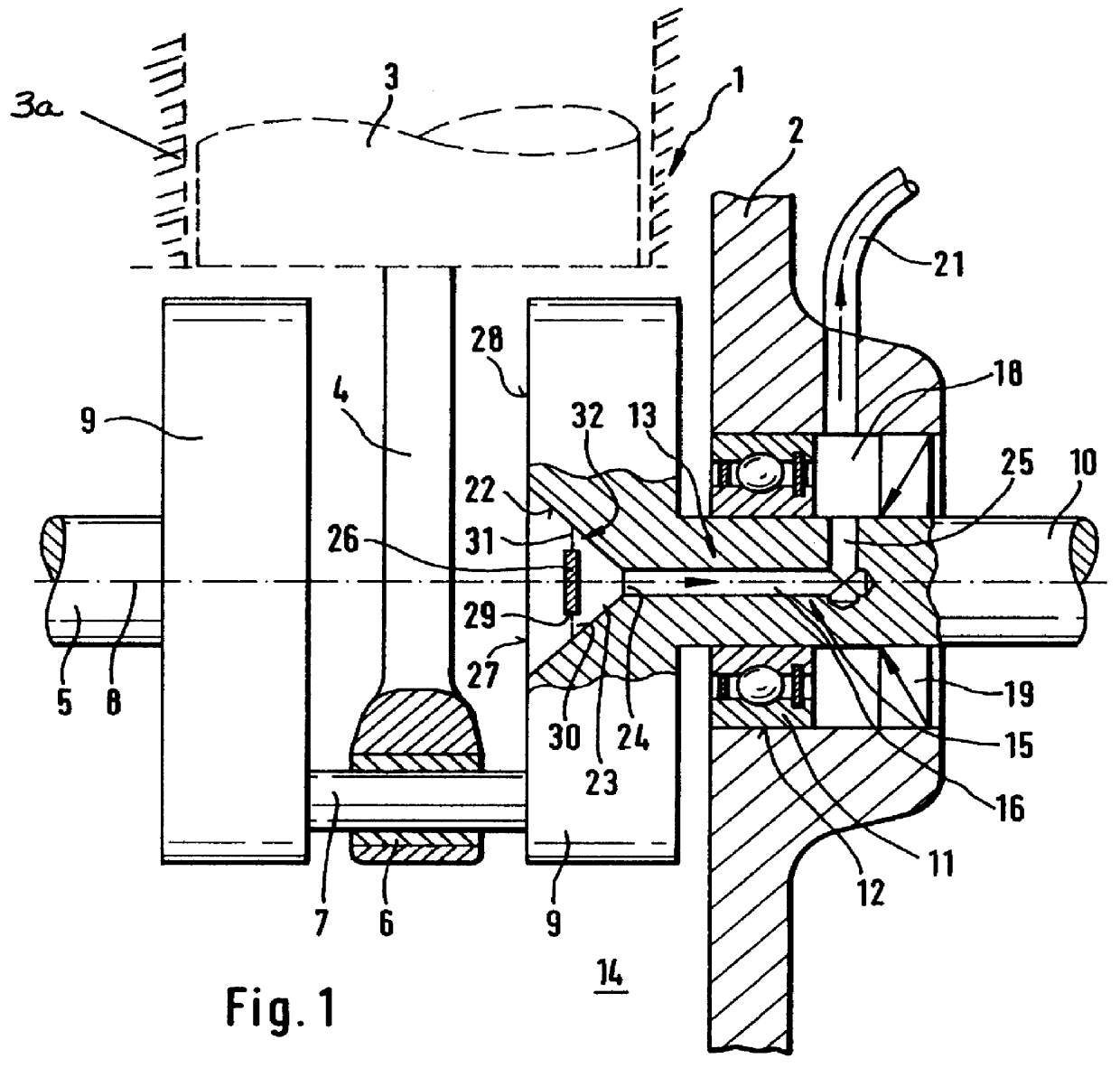
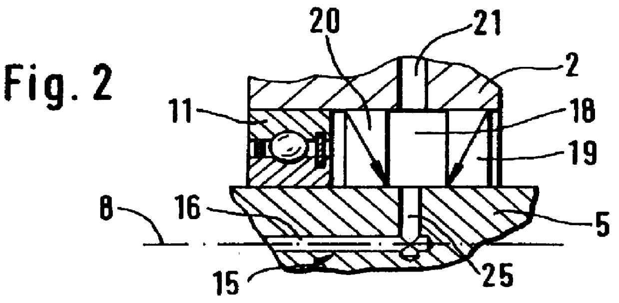
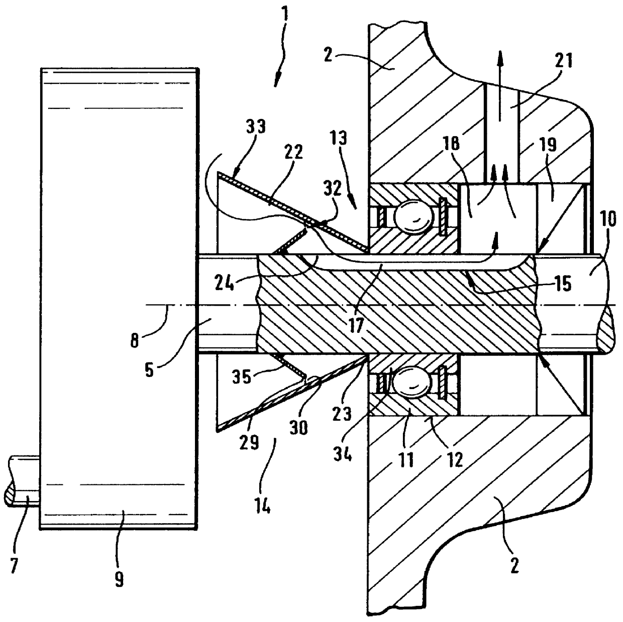
The crankcase 2 represented in FIG. 1 is a component of known internal combustion engine 1 with a piston 3 that reciprocates within a cylinder 3a. The piston 3 is connected by a connecting rod 4 to a crankshaft 5 that is driven in rotation by the piston 3. The connecting rod 4 is secured with a connecting rod bearing 6 on the crank bolt 7 which is secured eccentrically to the longitudinal axis 8 of the crankshaft 5 between two crank arms 9. The crankshaft 5 is secured at its ends 10 in crankshaft bearings 11 which are inserted into bearing housings 12 of the crankcase 2. The crankcase bearings 11 in the shown embodiment are roller bearings. In FIGS. 1 and 3, only one end 10 of the crankshaft 5 supported in the crankshaft bearing 11 is represented.

For pressure compensation within the crankcase 2, a crankcase venting device 13 is provided which has a venting l...


PUM


Abstract

An internal combustion engine has a reciprocating piston moving in a cylinder. A crank shaft is mounted in the interior of the crankcase. A connecting rod connects the piston to the crankshaft. The crankcase has a venting device for pressure compensation of the interior of the crankcase. The venting device has a venting line having a channel extending in a rotary component of the engine.

Description

BACKGROUND OF THE INVENTIONThe present invention relates to an internal combustion engine having a reciprocating piston which is connected by a connecting rod to a crankshaft for driving further rotary components of the motor. The crankshaft is supported in a crankcase that is provided with a venting device for pressure compensation in the interior of the crankcase, whereby the venting device has a venting line extending outwardly from the interior of the crankcase.In such internal combustion engines, especially four-stroke engines or engines of similar construction having a separate lubrication system, it must be ensured for proper functioning that over the course of time no impermissibly high pressure will be built in on the interior of the crankcase. It is thus known to provide the crankcase with a compensation system by which the excess pressure within the crankcase can be released to the atmosphere. However, since in the crankcase oil mist is present, it must be ensured that oi...

Claims


Application Information

Patent Timeline
IPC IPC(8): F01M13/04F01M13/00F01M1/06
CPCF01M1/06F01M13/04F01M2013/0422
Inventor HABERLEIN, JURGENBECKER, GEORGEBERHARDT, MAXIMILIAN
Owner ANDREAS STIHL AG & CO KG
Why Eureka
Try Eureka