Lamp with petaline reflector and aspheric lenses

a technology of aspheric lenses and reflectors, which is applied in the field of lamps, can solve the problems of reducing the transparency of the lens, affecting the performance of the lamp, and unable to provide enhanced clarity and depth, and achieves the effect of brighter lamps, effective improvement of the performance of the lamp, and increasing the coefficient of use of a luminous flux

Inactive Publication Date: 2000-08-29
STANLEY ELECTRIC CO LTD
View PDF3 Cites 47 Cited by
  • Summary
  • Abstract
  • Description
  • Claims
  • Application Information

AI Technical Summary

Benefits of technology

Another object of the present invention is to provide a lamp having a light distribution property free from constraints and exhibiting enhanced flexibility for a light distribution property, particularly in the horizontal direction.
If the aspheric lens is formed in a Fresnel configuration, an appearance like crystal glass can be obtained. Thus, the present invention offers wider design variations to a lamp and achieves an excellent effect in improving the marketability of the lamp.

Problems solved by technology

This degrades the transparency of the lens and makes it impossible to provide an appearance with enhanced clarity and sense of depth, which is currently preferred on the market.
However, since the composite reflecting surface 82 positioned at a recessed portion forms a light distribution property, the formation of the light distribution property is limited by such a factor as difficulty in determining the light distribution property in the direction of width.
Therefore, the lamp 70 used as a headlight is inferior in visibility when viewed from an oncoming vehicle.
Hence, it is impossible to distinguish them from other items and achieve novelty in terms of design.

Method used


Image

  • Lamp with petaline reflector and aspheric lenses
  • Lamp with petaline reflector and aspheric lenses
  • Lamp with petaline reflector and aspheric lenses

Examples


first embodiment

Each of the reflecting surface units 3a is obtained by cutting, from the spheroid RO1, a portion having a vertex at the point of intersection of the spheroid RO1 and the bulb center axis X and spanning a range of 15.degree. to 60.degree. around the bulb center axis X such that the cut portion is bilaterally symmetrical with respect to the oblique line Y (long axis). In cutting the portion, the inner side of the spheroid RO1 is used as the reflecting surface. The first embodiment has adopted the spheroid RO1 that has been cut at the position at which the reflecting surface appears when viewed from the front side of the lamp 1. The plurality of reflecting surface units 3a thus obtained are combined with each other to form the petaline reflector 3. In the present invention, four to ten reflecting surface units 3a are preferably combined.

To correspond to the respective second focal points F2 of the reflecting surface units 3a, the aspheric lenses 4 having respective focal lengths of 10 ...

second embodiment

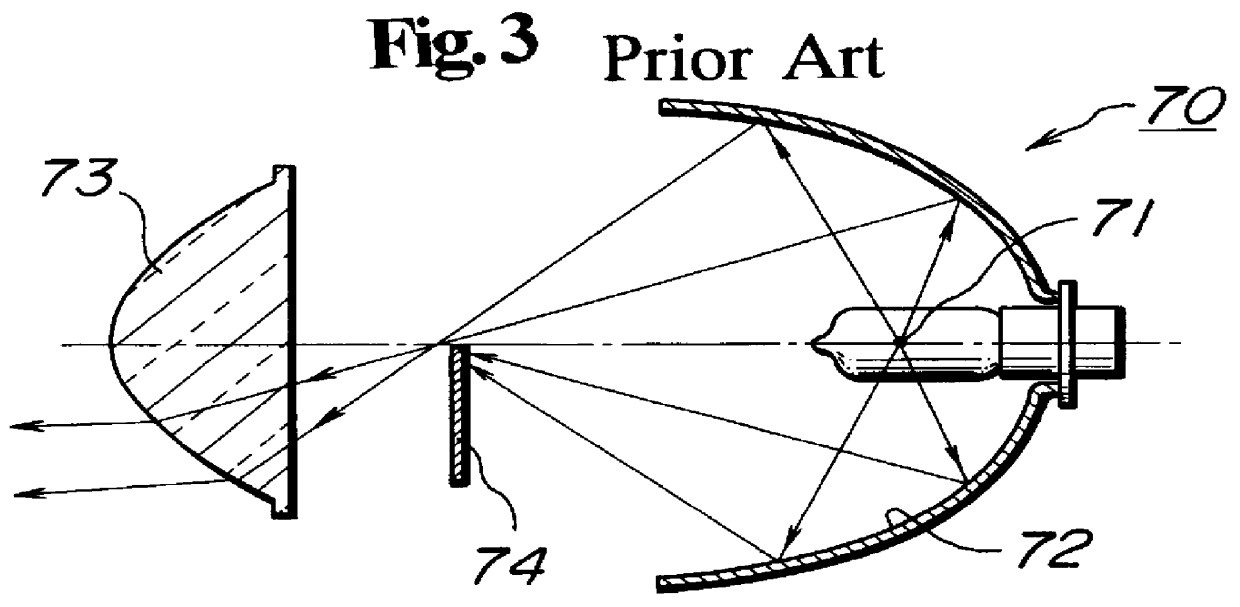
The second embodiment has been implemented in view of the foregoing and the reflecting surface unit 13a is configured as an elliptic free-form surface (composite elliptic surface) such that a second focal point F4 linearly expands in the horizontal direction. Since means for forming the reflecting surface from the elliptical free-form surface has widely been used in the conventional projector type lamp (see FIG. 3), the detailed description thereof is omitted here.

A plurality of reflecting surface units 13a each configured as an elliptic free-form surface having such a second focal point as to linearly expand in the horizontal direction are combined with each other to form a petaline reflecting surface 13. In the lamp 1 of the second embodiment thus structured, a basic light distribution property has a generally elliptic configuration with a long axis extending in the horizontal direction, which compensates for the insufficient width of the illuminating light beam in the horizontal ...


PUM


Abstract

A lamp including a light source, a petaline reflector, and aspheric lenses. The petaline reflector is formed of a plurality of reflecting surface units combined radially around the center axis of the light source. Each of the reflecting surface units is obtained by cutting, radially around the center axis, a portion from a spheroid having a first focal point located on the center axis and adjacent the light source and a second focal point located on a line passing through the first focal point and tilted appropriately from the center axis such that the cut portion spans a range of 15.degree. to 60.degree. around the center axis. The aspheric lenses are disposed to correspond to the respective second focal points of the reflecting surface units of the petaline reflector and converge reflected light beams from the respective reflecting surface units. Shades for forming a light distribution pattern are disposed at the respective near-focal points of the aspheric lenses.

Description

BACKGROUND OF THE INVENTION1. Field of the InventionThe present invention relates to a lamp and, more particularly, to a lamp suitable for use as an illumination lamp for a vehicle such as a head lamp or fog lamp, a signal lamp for a vehicle such as a tail lamp or turn signal lamp, a signal lamp for road traffic, or a signal lamp for railway traffic.2. Background ArtFIGS. 1 to 3 show conventional lamps of this type. A lamp 90 shown in FIG. 1 basically includes: a light source 91; a revolutional paraboloidal reflector 92 having the light source 91 disposed at a focal point thereof; and a lens 93 with a lens cut 93a. A light beam from the light source 91 is reflected by the revolutional paraboloidal reflector 92 to form a parallel light beam. The reflected light beam is diffused properly by the lens cut 93a of the lens 93 to provide a desired light distribution property.A lamp 80 shown in FIG. 2 includes a light source 81; a reflector composed of a composite reflecting surface 82; and...

Claims


Application Information

Patent Timeline
Patent Type & Authority Patents(United States)
IPC IPC(8): F21V5/00F21V7/00F21S8/12F21V11/16F21V11/00F21S8/10F21V5/04F21S8/00F21V11/14F21V13/04F21V13/12F21V13/00F21S2/00
CPCF21S48/1275F21S48/1283F21S48/1376F21S48/145F21S48/24F21V5/04F21V5/045F21V11/14F21V13/12F21W2111/00F21S41/265F21S41/275F21S41/337F21S41/43F21S43/40B60Q1/00
Inventor FUTAMI, TAKASHIKOIKE, TERUOKAWAGUCHI, YOSHIFUMI
Owner STANLEY ELECTRIC CO LTD
Why Eureka
Try Eureka