Multiple polarity mask exposure method

a mask and multipolarity technology, applied in the field of mask formation, can solve the problems of pattern formation, clear defects sometimes occur when forming positive resists, and opaque defects sometimes occur when patterning,

Inactive Publication Date: 2000-08-29
IBM CORP
View PDF5 Cites 25 Cited by
  • Summary
  • Abstract
  • Description
  • Claims
  • Application Information

AI Technical Summary

Problems solved by technology

However, opaque defects sometimes occur when patterning and exposing the negative resist when foreign material resides within the resist film or foreign material remains on the substrate after processing.
Similarly, clear defects sometimes occur when forming the positive resist when foreign material resides on or in the resist film or a concentrated develop chemical attacks the resist.
Such defects result in improperly formed or etche

Method used


Image

  • Multiple polarity mask exposure method
  • Multiple polarity mask exposure method
  • Multiple polarity mask exposure method

Examples


Embodiment Construction

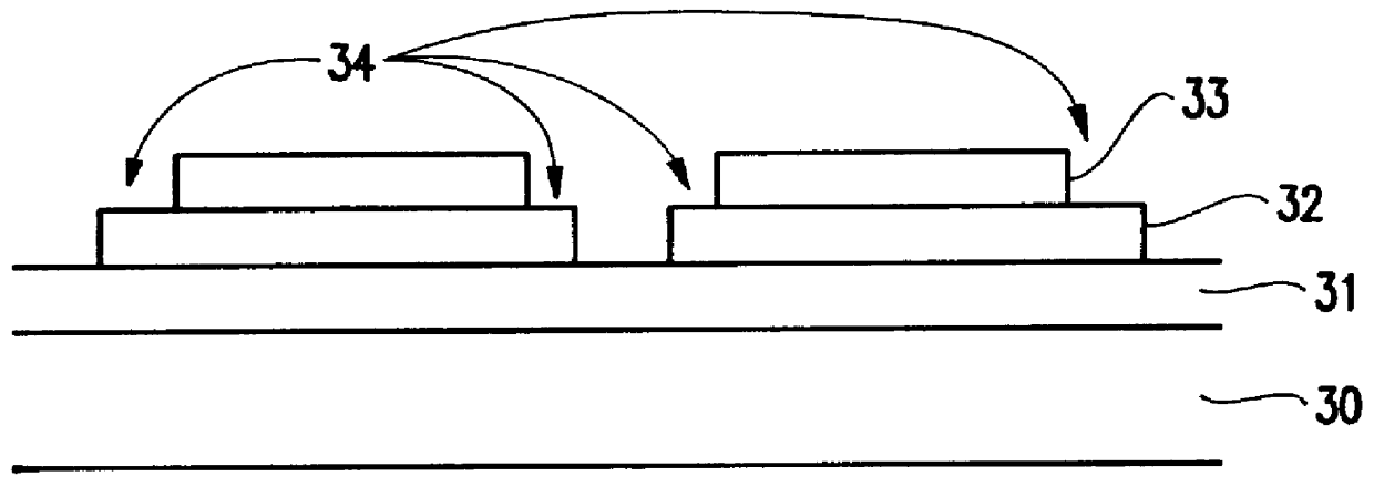
Referring now to the drawings, and more particularly to FIG. 3, a first embodiment of the invention is illustrated. More specifically, FIG. 3 illustrates a substrate 30 (such as a quartz layer), a second layer 31 (such as a chrome layer) which is to be patterned, a first resist layer 32 such as a negative resist layer and a second resist layer 33 which has an opposite polarity when compared to the first resist layer 32, such as a positive resist material. In the example shown in FIG. 3, the first and second resists 32, 33 will be used as a mask to etch the second layer 31.

The substrate 30, second layer 31, first resist 32 and second resist 33 can be formed using techniques well known to those ordinarily skilled in the art. For example, if the substrate 30 is a quartz layer, the quartz can be formed by cutting and polishing a quartz ignote. Similarly, if the second layer 31 is a chrome layer, it can be formed by spluttering, chemical vapor deposition, plasma enhanced chemical vapor d...


PUM


Abstract

A patterned mask and method of forming a patterned mask over a substrate, comprising forming a first resist layer over the substrate, forming a second resist layer over the first resist layer, patterning the first resist using energy selective to the first resist layer to form a first patterned resist, and patterning the second resist using energy selective to the second resist layer to form a second patterned resist, wherein the first patterned resist and the second patterned resist form the patterned mask.

Description

1. Field of the InventionThe present invention generally relates to the formation of patterns on semiconductor substrates and more specifically to a method of forming masks, such as chrome masks on quartz, with a reduced defect rate.2. Description of the Related ArtConventional systems utilize positive tone resist materials, including, but not limited to, high polymer organic films or negative resists materials including, but not limited to, high polymer organic films. A pattern is exposed on the positive or negative resists using an electromagnetic source, such as a laser beam or electron beam. When the positive resist is developed the exposed portions become soluble and are removed with a solution such as an alkaline or solvent solution. Similarly, when the negative resist is developed the unexposed portions become soluble and are removed with a solution such as an alkaline or solvent solution. Therefore, as is well known to those ordinarily skilled and the art, a positive or nega...

Claims


Application Information

Patent Timeline
IPC IPC(8): G03F7/095G03F7/20H05K3/06
CPCG03F7/095G03F7/2022G03F7/2037H05K3/064H05K2203/0505H05K2203/0577G03F1/50
Inventor HIBBS, MICHAEL S.NEARY, TIMOTHY E.O'GRADY, DAVID S.RIGAILL, DENIS M.
Owner IBM CORP
Why Eureka
Try Eureka