Furnace exhaust method and apparatus

a technology of furnace exhaust and exhaust pipe, which is applied in the direction of ovens, lighting and heating apparatus, ovens, etc., can solve the problems of physical damage and deterioration of electrical heating elements, and not completely solved

Inactive Publication Date: 2000-08-29
CRESS STEVEN B
View PDF4 Cites 3 Cited by
  • Summary
  • Abstract
  • Description
  • Claims
  • Application Information

AI Technical Summary

Problems solved by technology

In the furnace arts, and particularly high temperature furnaces such as electrically heated ceramic kilns and the like, a continuing problem is physical damage to, and deterioration of, the electrical heating elements by reason of the elements operating in an atmosphere contaminated with products of combustion and gasses re

Method used


Image

  • Furnace exhaust method and apparatus
  • Furnace exhaust method and apparatus
  • Furnace exhaust method and apparatus

Examples


Embodiment Construction

An inventory of items bearing reference numerals on the accompanying drawings:

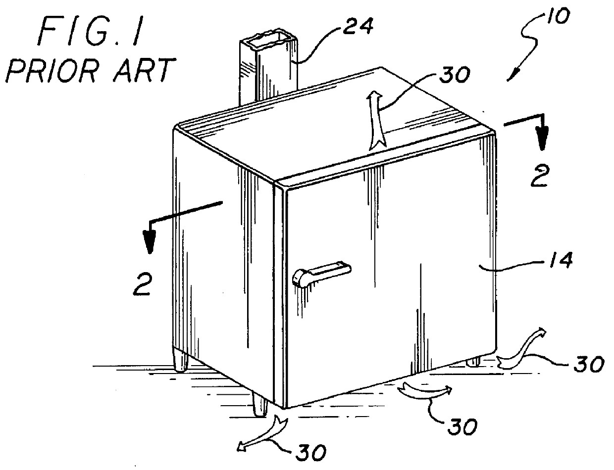
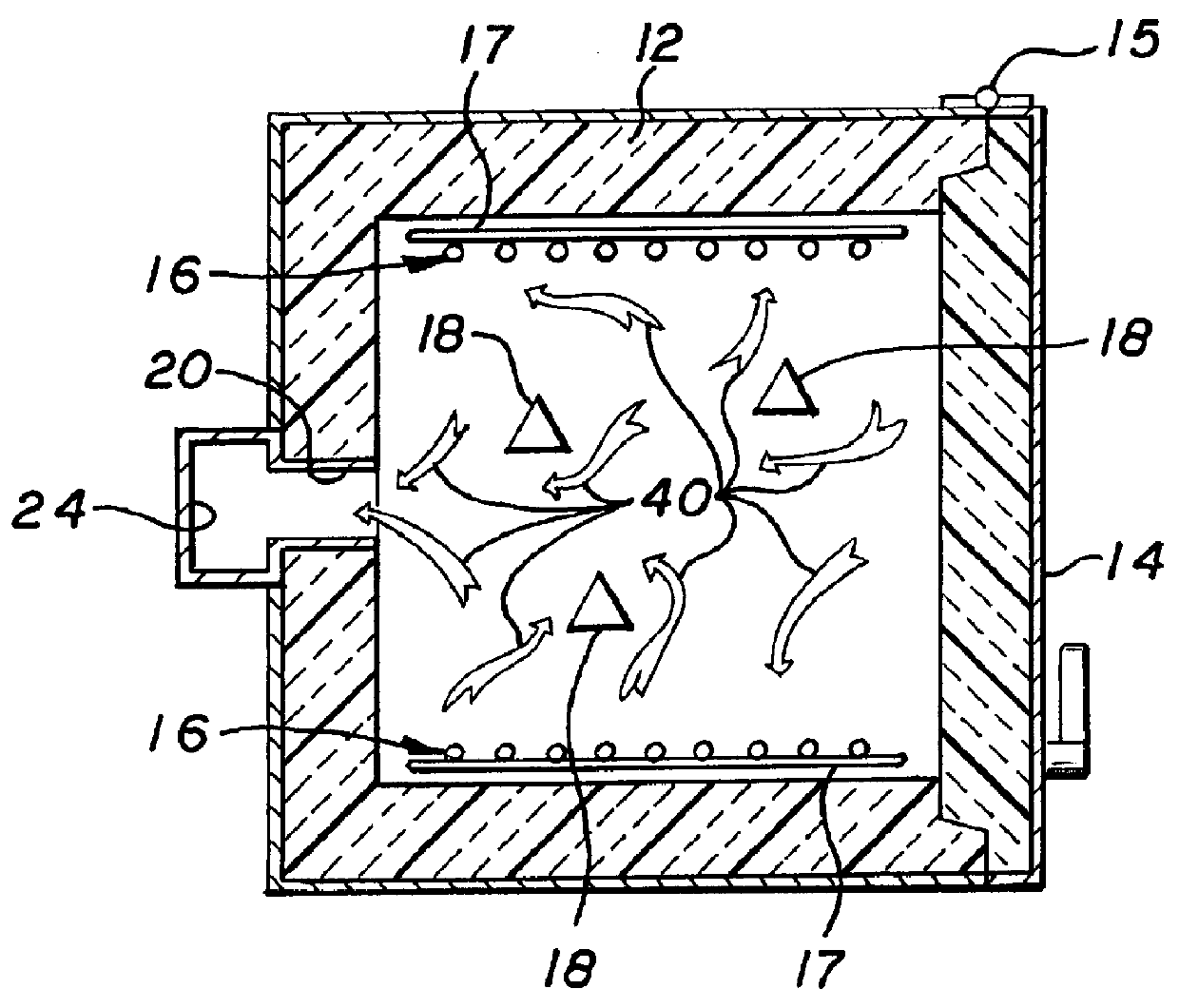
FIGS. 1 and 2 show schematically a high temperature furnace and the air flow through the furnace according to the art prior to my present invention. A furnace 10, shown here as a cube, is formed with insulated walls 12, an insulated door 14, and an exhaust stack 24 for exhaust gasses. In operation there will be articles 18 within the furnace, which articles are subjected to heating in the furnace. Electrical heating elements 16 will be mounted on a backing and support member 17. The electrical heating elements 16 face the articles being subjected to heat. Contaminated heated air 40 containing various corrosive impurities will circulate throughout the furnace and in contact with all surfaces including the electrical heating elements as is known to those skilled in the art. The contaminated air coats the heating elements with impurities and causes corrosion and ultimate failure of the heating elements.

In som...


PUM

PropertyMeasurementUnit
Pressureaaaaaaaaaa
Heataaaaaaaaaa

Abstract

An electrically heated furnace wherein electrical heating elements are mounted and supported so that they face the inner furnace walls and are isolated from direct communication with articles being treated within the furnace such that clean air flows over the heating elements providing oxygen to create an aluminum oxide coating on the heating elements and maintains a clean atmosphere about the heating elements. Air circulation from exterior the furnace is through ports in the furnace walls and over the electrical heating elements; exhaust from the furnace is through ports in the furnace walls into a plenum and out through a flue creating pressure differentials with the pressure in the furnace area where articles are being subjected to heat is lower than the atmosphere and the area in which the heating elements are located.

Description

1. Field of the InventionThis invention is in the general field of electrically heated furnaces and the like;The invention is more particularly directed to methods and apparatus relating to circulation of air and products of combustion in furnaces and the like;The invention is most particularly in the field of a new and unique method of circulating air and exhausting air and the like from furnaces and the like in a manner which protects electrical heating elements and the like and which enables a greater uniformity and control of heat within the furnace.2. Description of the Prior ArtThere have been various attempts to create systems for improved air circulation and protection of electrical heating elements in electrically heated furnaces and the like. My invention of the system set forth in my above referenced U.S. Pat. No. 5,378,144 was a significant advance in the art.There continued to be a need for further improvement in the art of circulation of heated air and the exhaust of c...

Claims


Application Information

Patent Timeline
IPC IPC(8): C03B29/00C03B29/02F27D1/00F27D11/00F27B17/00F27D7/00F27D11/02F27D7/04
CPCC03B29/02F27B17/0083F27D1/0036F27D7/04F27D11/02
Inventor CRESS, STEVEN B.
Owner CRESS STEVEN B
Why Eureka
Try Eureka