Phase-locked loop circuit with dynamic backup

a loop circuit and phase lock technology, applied in the field of phase lock loop circuits with dynamic backup, can solve the problems of the output signal of the pll circuit to lose lock with the input reference signal, the performance of the pll circuit is notoriously sensitive to environmental influences,

Inactive Publication Date: 2000-08-29
IBM CORP
View PDF10 Cites 32 Cited by
  • Summary
  • Abstract
  • Description
  • Claims
  • Application Information

AI Technical Summary

Problems solved by technology

Typically, both the low-pass filter and the VCO of a PLL circuit employ analog components, and because of these analog components, PLL circuits are notoriously sensitive to environmental influences.
In addition, there are also other sources that affect the performance of a PLL circuit, for example, a noisy or missing input reference signal, a noisy or missing output signal, a noisy or insufficient power supply to the PLL circuits, or extraneous noise picked up by the PLL circuit.
Quite often, any one or more of the above factors may lead the PLL circuit output signal to lose lock with the input reference signal.

Method used


Image

  • Phase-locked loop circuit with dynamic backup
  • Phase-locked loop circuit with dynamic backup
  • Phase-locked loop circuit with dynamic backup

Examples


Embodiment Construction

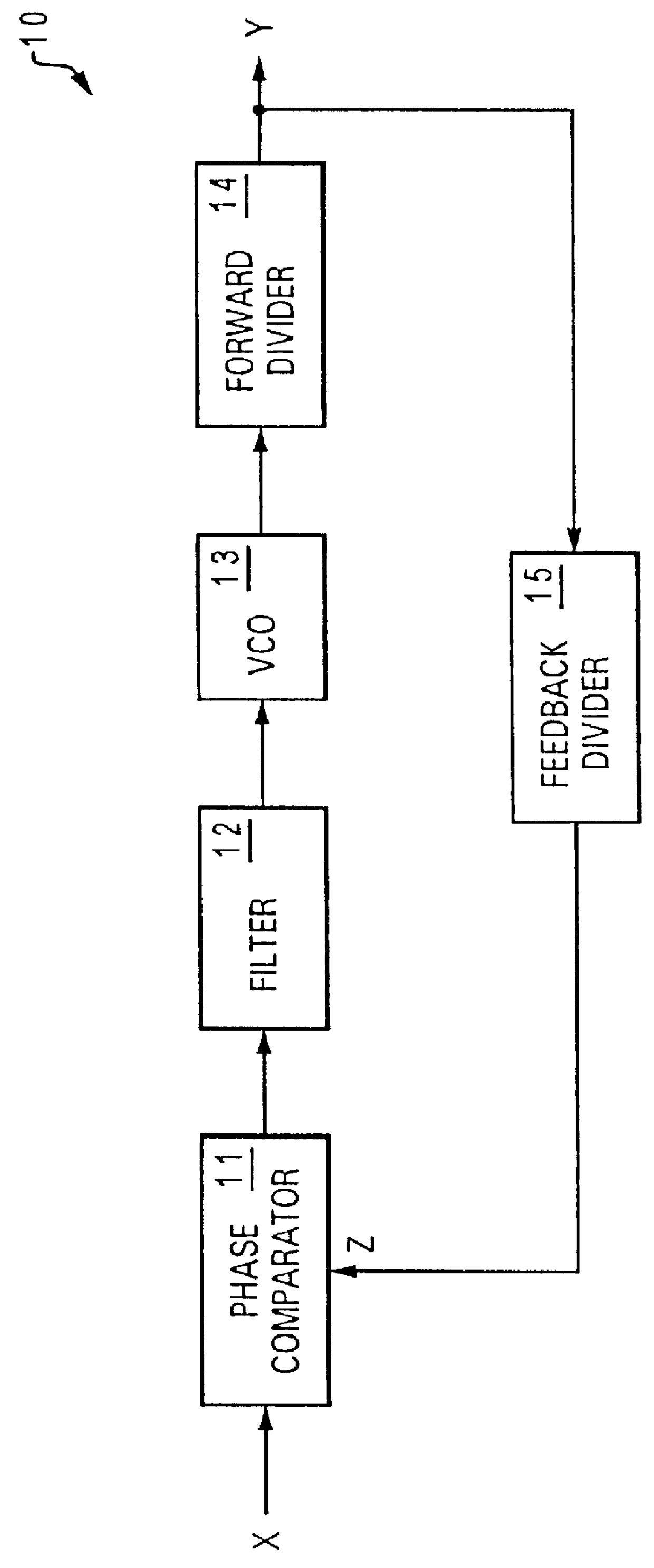
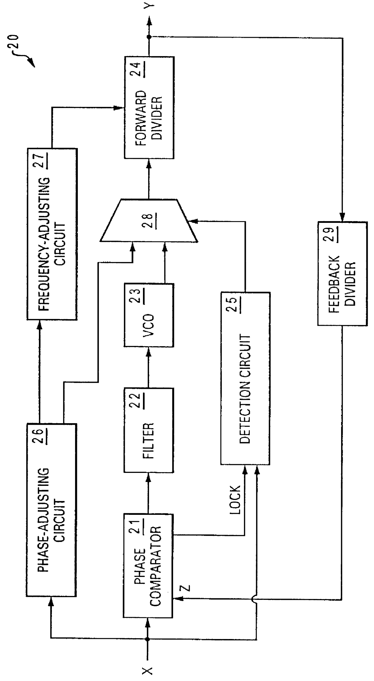
Referring now to the drawings and in particular to FIG. 1, there is depicted a block diagram of a conventional phase-locked loop (PLL) circuit. As shown, PLL circuit 10 includes a phase comparator 11, a lowpass filter 12, a voltage-controlled oscillator (VCO) 13, a forward divider 14, and a feedback divider 15. Phase comparator 11 compares the phases of an input reference signal X and a feedback signal Z to generate a voltage signal representing the phase difference between reference signal X and feedback signal Z. The voltage signal output from phase comparator 11 is then sent to VCO 13 via lowpass filter 12. A division operation is next performed on an output signal generated by VCO 13, utilizing forward divider 14. Forward divider 14 divides the output signal received from VCO 13 by a predetermined value. The output signal Y of forward divider 14 is subsequently sent back to phase comparator 11 via a feedback divider 15 as feedback signal z.

Output signal Y is generated on the bas...


PUM


Abstract

A phase-locked loop circuit with dynamic backup is disclosed. The phase-locked loop circuit with dynamic backup includes a phase comparator, a lowpass filter, a voltage-controlled oscillator, and a detection circuit. The phase comparator compares an input reference signal and a feedback output signal from an output of the phase-locked loop circuit for generating a voltage signal representing the phase difference between the input reference signal and the feedback output signal. After the voltage signal is filtered by the lowpass filter, the filtered voltage signal is sent to the voltage-controlled oscillator for generating the feedback output signal. Coupled to the phase comparator, the detection circuit detects whether or not the phase-locked loop circuit is in lock with the input reference signal. In response to a determination that the phase-locked loop circuit is not in lock with the input reference signal, the detection circuit directs the input reference signal to bypass the phase comparator, the lowpass filter, and the voltage-controlled oscillator.

Description

1. Technical FieldThe present invention relates to an apparatus for synthesizing signals in general, and in particular to a phase-locked loop circuit. Still more particularly, the present invention relates to a phase-locked loop circuit with dynamic backup.2. Description of the Prior ArtPhase-locked loop ("PLL") circuits are electronic circuits utilized for locking an output signal in phase and frequency with a reference signal. Traditionally, PLL circuits are found in a variety of data communication devices and telecommunication devices for generating a clock signal synchronous to an external clock signal. In recent years, PLL circuits have often been employed in data processing systems and microprocessors for the purpose of generating a local clock signal that is phase-aligned with a reference clock signal generated by a crystal or another PLL circuit. A common reason for utilizing a PLL circuit within a data processing system is that a PLL circuit is able to synthesize a very sta...

Claims


Application Information

Patent Timeline
Patent Type & Authority Patents(United States)
IPC IPC(8): G06F1/10H03L7/08H03L7/095H03L7/16H03L7/183H03L7/087H03L7/10
CPCG06F1/10H03L7/095H03L7/183Y10S331/02H03L7/08
Inventor AULET, NANCY RUTHBEERS, GREGORY EDWARD
Owner IBM CORP
Why Eureka
Try Eureka