Process of making fine and ultra fine metallic fibers

a technology of metallic fibers and cladding materials, applied in the field of metal fibers, can solve the problems of requiring a three-cladding process, initial diameter of metallic wires, incomplete removal of cladding materials from metallic fibers during the leaching process,

Inactive Publication Date: 2000-09-05
PALL CORP
View PDF27 Cites 59 Cited by
  • Summary
  • Abstract
  • Description
  • Claims
  • Application Information

AI Technical Summary

Problems solved by technology

Although the foregoing process of making fine metallic fibers has been found satisfactory in the prior art, the process has certain disadvantages for some applications.
The first disadvantage is the requirement of incorporating a three cladding process in order to produce metallic fibers in the range of 6 microns in diameter.
Another limitation is the initial diameter of the metallic wire must be of a sufficient size in order to clad carbon steel thereto.
Another disadvantage of the aforementioned process includes the incomplete removal of the cladding material from the metallic fibers during the leaching process.
Another disadvantage of this prior art process is the diffusion of impurities of the carbon steel into the metallic fibers during the drawing process.
A substantial amount of heat and pressure are produced during the drawing process causing a fusion of undesirable materials from the carbon steel upon the surface of the metallic fibers.
In certain applications, these undesired impurities are detrimental to the application and the use of the metallic fibers.
For example, these undesirable impurities may be detrimental when the metallic fibers are used in a filtration process or the like.
Although the aforementioned processes have provided high quality metallic fibers in the desired diameter range, the aforementioned processes still suffer from certain deficiencies.
Firstly, the process of multiple claddings in one example incorporates the use of carbon steel cladding of stainless steel fibers.
Unfortunately, the removal of carbon steel cladding material from stainless steel wire or fibers is a costly, time consuming and an environmentally unfriendly process.
Another disadvantage of the aforementioned process when making stainless steel fibers through the use of a carbon steel cladding is the involved chemical process for removing the carbon steel cladding from the stainless steel fibers.
A further disadvantage of the prior art process is the amount of unusable byproducts from the carbon steel removed from the stainless steel to produce the fine metallic fibers.

Method used


Image

  • Process of making fine and ultra fine metallic fibers
  • Process of making fine and ultra fine metallic fibers
  • Process of making fine and ultra fine metallic fibers

Examples


Embodiment Construction

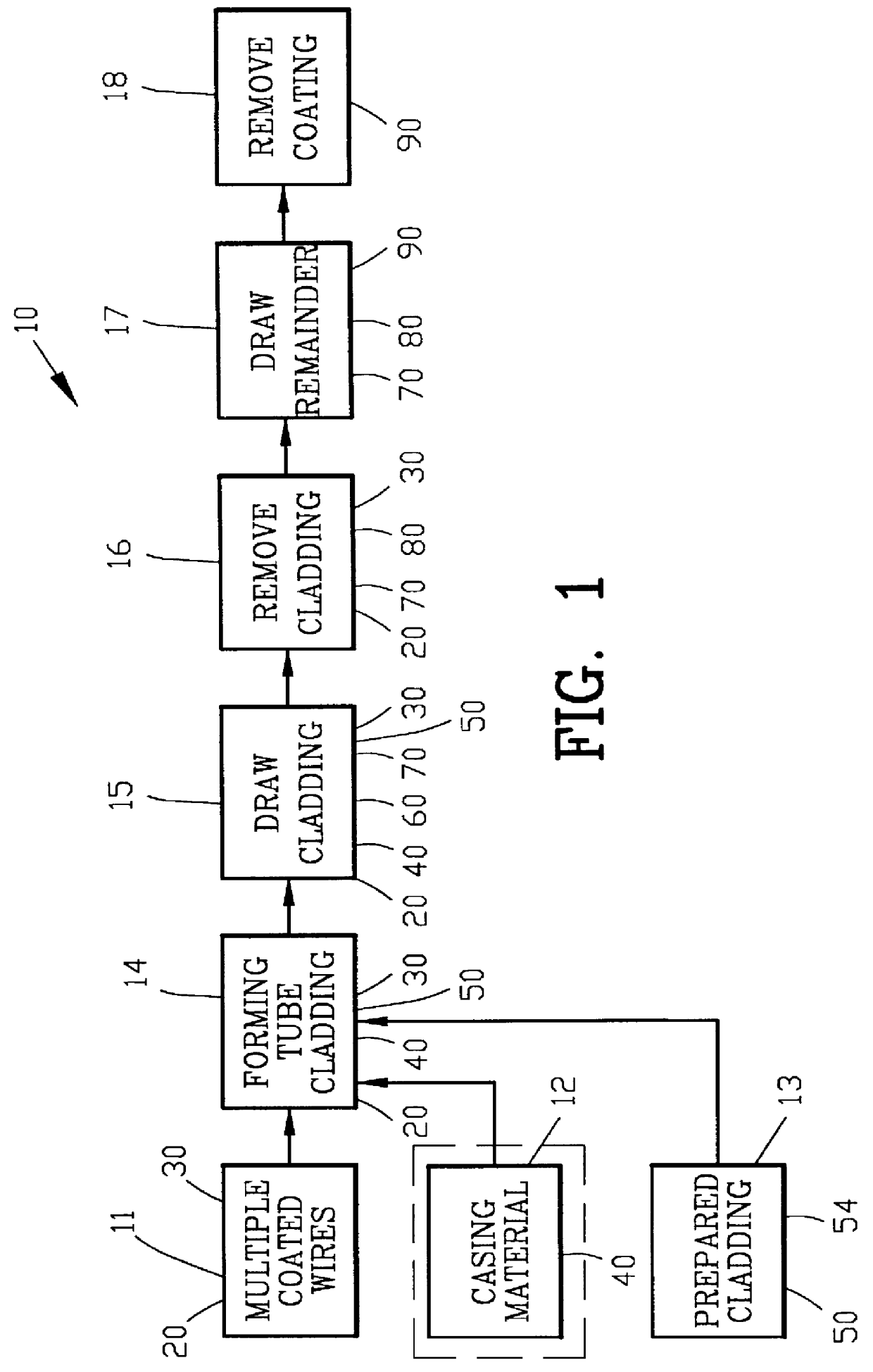
FIG. 1 is a block diagram illustrating an improved process 10 for making fine metallic fibers. The improved process 10 of FIG. 1 comprises the process step 11 of providing multiple coated metallic wires 20 with each of the metallic wires 20 having a coating material 30.

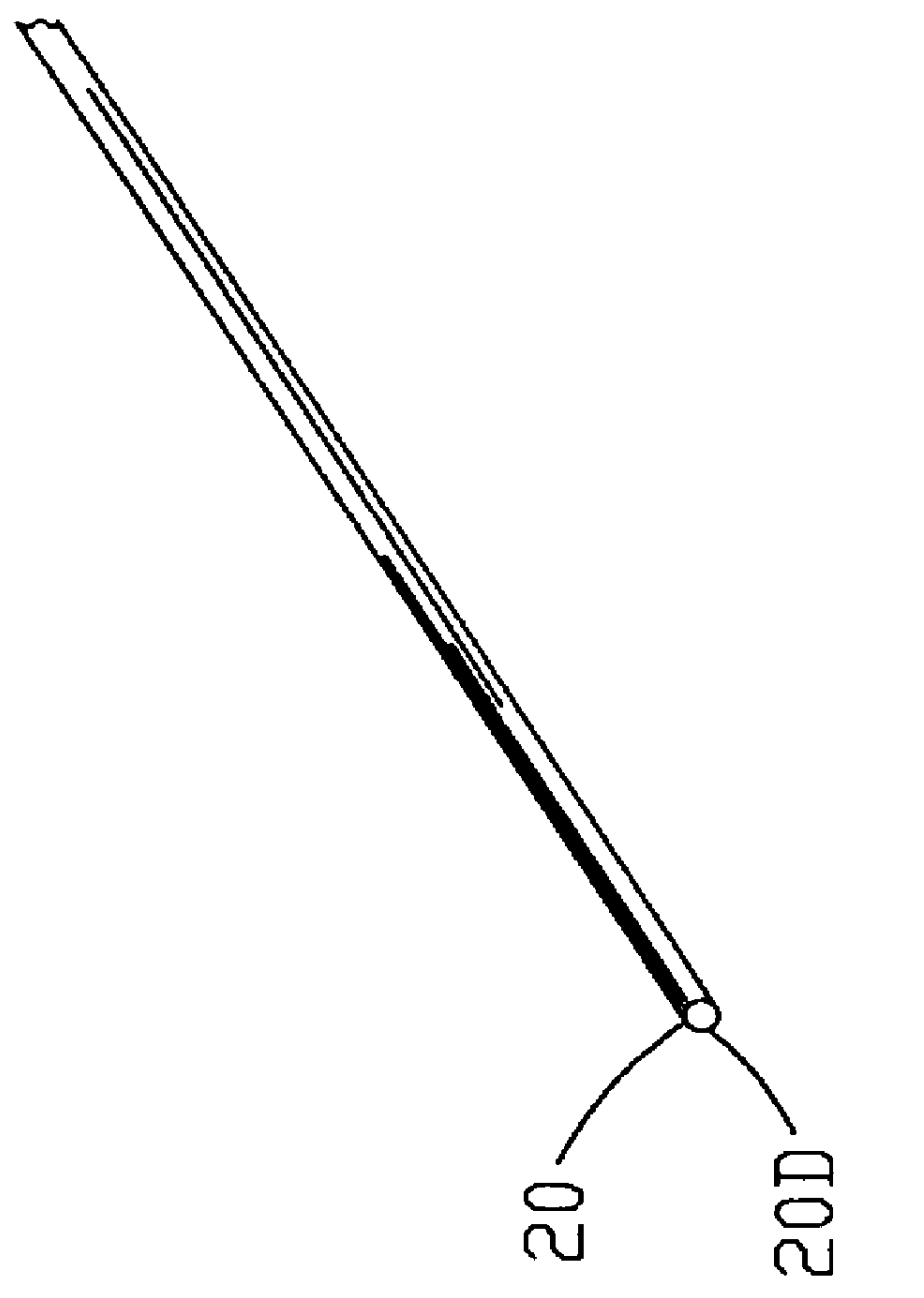
FIG. 2 is an isometric view of the metallic wire 20 referred to in FIG. 1 with FIG. 2A being an enlarged end view of FIG. 2. In this example, the metallic wire 20 is a stainless steel wire having a diameter 20D but it should be understood that various types of metallic wires 20 may be used in the improved process 10.

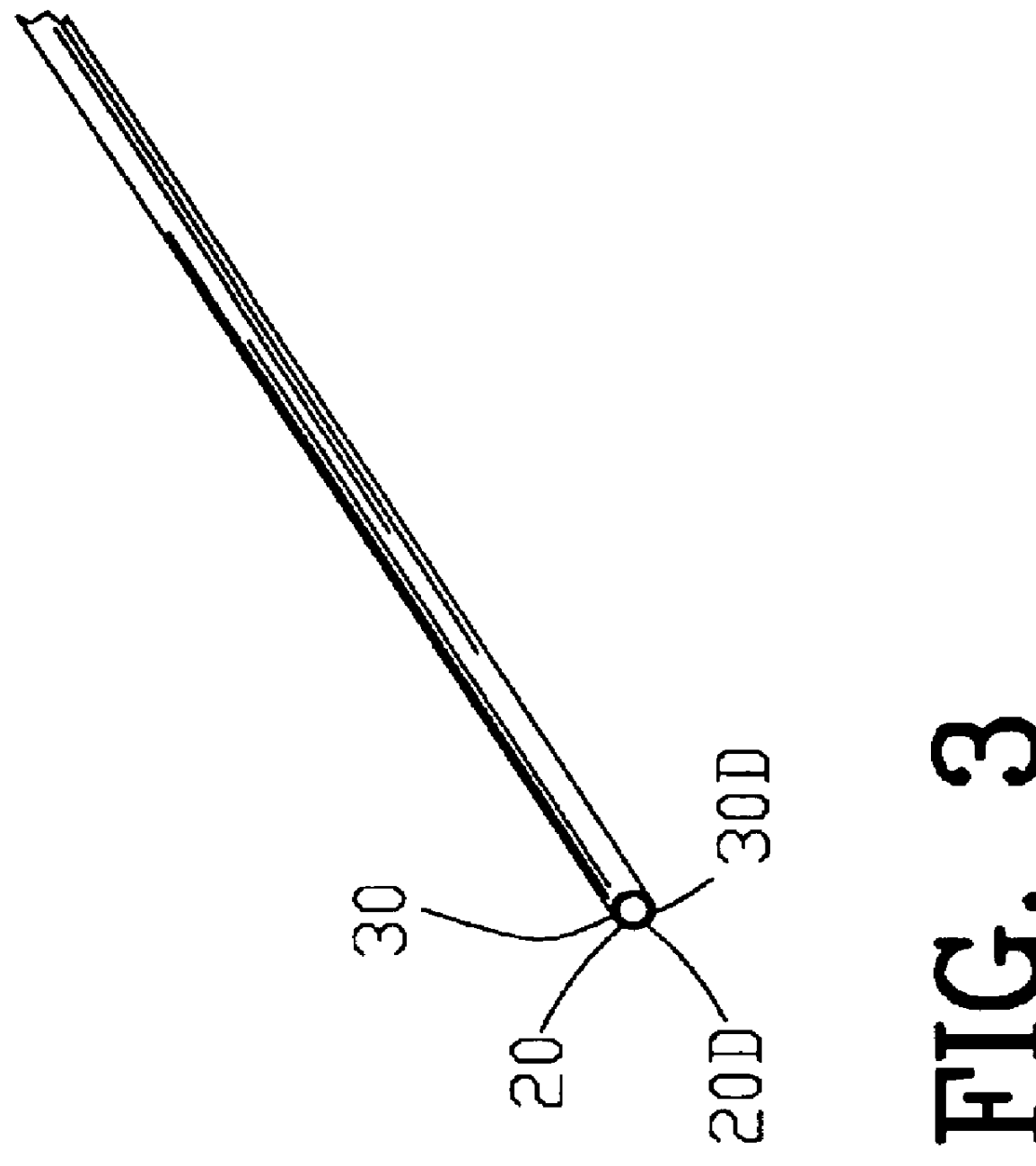
FIG. 3 is an isometric view of the metallic wire 20 of FIG. 2 with the coating material 30 thereon. FIG. 3A is an enlarged end view of FIG. 3. In this example, the coating material 30 is a copper material but it should be understood that various types of coating materials 30 may be used in the improved process 10.

The process of applying the coating material 30 to the metallic wire 20 may be accomplished in...


PUM

PropertyMeasurementUnit
diameteraaaaaaaaaa
diameteraaaaaaaaaa
diameteraaaaaaaaaa

Abstract

A process is disclosed for making fine metallic fibers comprising forming a continuous tube about a plurality of coated metallic wires for providing a first cladding. The first cladding is drawn for reducing the outer diameter and for diffusion welding the coating within the cladding. The tube is mechanically removed to provide a first remainder. The first remainder is drawn for reducing the diameter thereof to transform the plurality of metallic wires into a plurality of fine metallic fibers. In one example, the diffusion welded coating is removed for providing the plurality of fine metallic fibers. In another example, a plurality of the first remainders are assembled and a continuous tube is formed about a the first remainders for providing a second cladding. The second cladding is drawn for reducing the outer diameter. The tube is mechanically removed to provide a second remainder. The second remainder is drawn for reducing the diameter thereof to transform the plurality of fine metallic fibers into a plurality of ultra fine metallic fibers. The diffusion welded coating is removed for providing the plurality of ultra fine metallic fibers.

Description

1. Field of the InventionThis invention relates to metallic fibers and more particularly to an improved method of making fine and ultra fine metallic fibers through a new cladding and drawing process.2. Background of the InventionIn recent years, the need for high quality, small diameter metallic fibers has grown as new applications for such fibers are developed by the art. High quality, small diameter metallic fibers have been used in diverse applications such as filtration media as well as being dispersed within a polymeric material to provide electrostatic shielding for electronic equipment and the like. This need for high quality, small diameter metallic fibers has produced various new ways and processes for making these high quality metallic fibers for the various uses in the art.Typically, high quality metallic fibers may be characterized as small diameter metallic fibers having a diameter of less than 50 micrometers with a substantially uniform diameter along the longitudinal...

Claims


Application Information

Patent Timeline
Patent Type & Authority Patents(United States)
IPC IPC(8): B21C37/00B21C37/04B22F1/00B22F1/062
CPCB21C37/047B22F1/004Y10T29/4981B22F2998/10Y10T29/49812Y10T29/49801Y10S29/011Y10S977/84Y10S977/762B22F2998/00Y10S977/89C25D7/00B22F3/20B22F9/16B22F1/0025B22F1/062B22F1/0547
Inventor QUICK, NATHANIEL R.LIBERMAN, MICHAELSOBOLEVSKY, ALEXANDERMCNEICE, RAYMOND R.
Owner PALL CORP
Why Eureka
Try Eureka