

Memory module with obstacle removing terminal structure
a terminal structure and memory module technology, applied in the field of memory modules, can solve problems such as ineffective elimination of possible connection failures, and achieve the effect of improving the terminal structur
- Summary
- Abstract
- Description
- Claims
- Application Information
AI Technical Summary
Benefits of technology
Problems solved by technology
Method used
Image

Examples
first embodiment
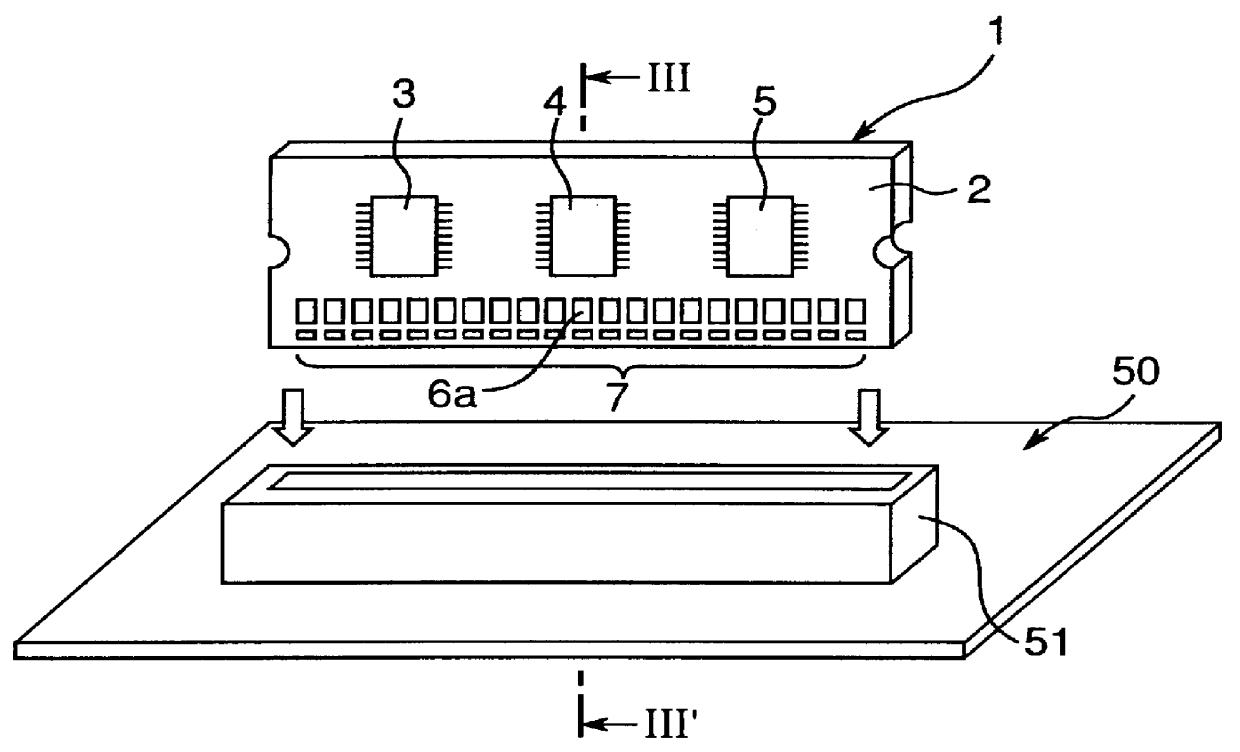
Referring to FIGS. 1 to 4, a printed circuit board 50 is shown to have the female socket 51 fixedly mounted thereon. As best shown in FIGS. 3 and 4, the female socket 51 is of a configuration having interior walls that are opposed to each other with a socket groove defined therebetween, and includes first and second arrays of equally spaced terminal tongues 52 and 53, each having a free end portion exposed to and resiliently deformably protruding into the socket groove. The female socket 51 of the structure discussed above is well known to those skilled in the art and, therefore, no further detail thereof will be discussed for the sake of brevity.
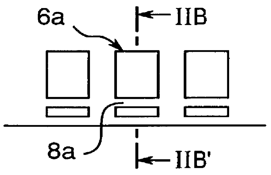
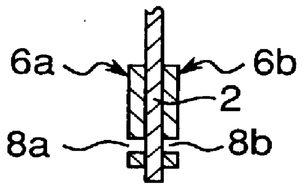
The memory module 1 comprises a generally rectangular substrate 2 having a plurality of, for example, three memory chips 3, 4 and 5 mounted on at least one surface thereof in side-by-side fashion in a direction longitudinally of the substrate 2. One of the opposite side portions of the substrate 2, or a lower edge portion of the substrate 2...
second embodiment
Referring to FIGS. 5A and 5B, the first and second arrays of the terminal strips are identified by 9a and 9b, respectively. In this embodiment, the obstacle removal portion defined in each of the terminal strips 9a and 9b comprises at least one generally U-shaped cutout 10a and 10b extending inwardly from one side of the respective terminal strip 9a and 9b in a direction perpendicular to the longitudinal sense of the terminal strip 9a and 9b so as to terminate at a location spaced a distance inwardly from the opposite side of the respective terminal strip 9a and 9b.
As is the case with the foregoing embodiment, the generally U-shaped cutouts 10a and 10b provide surface indentations in the terminal strips 9a and 9b and, therefore, the foreign matter 30 on the mating terminal tongue 52 or 53, can be trapped into the associated cutout 10a or 10b as the male connector 7 is inserted into the female socket 51.
The embodiment shown in FIGS. 5A and 5B brings about an additional advantage. The...
third embodiment
In the third embodiment of the present invention shown in FIGS. 8A and 8B, the obstacle removal portion defined in each of the terminal strips now identified by 15a and 15b on the opposite surfaces of the substrate 2 comprises at least one round hole 16a and 16b. The use of the round hole 16a and 16b is particularly advantageous in that the bondability of each terminal strip 15a and 15b to the associated surface of the substrate 2 will can be increased as compared with the obstacle removal portion of a kind which open to the outside at one side edge of the associated terminal strip.
Modification
FIGS. 9A and 9B illustrate a modification of the third embodiment. In this modification, the obstacle removal portion comprises a plurality of round holes 18a and 18b each defined in each of the terminal strips 17a and 17b on the respective surfaces of the substrate 2.
PUM
 Abstract
Description
Claims
Application Information