Method for reducing particulate generation from regeneration of cryogenic vacuum pumps

a cryogenic vacuum pump and particulate generation technology, applied in the direction of positive displacement liquid engine, separation process, lighting and heating apparatus, etc., can solve the problems of reducing the adsorption surface effect, deteriorating performance, and eventually becoming unacceptable, and sorbent material loses its adsorption ability

Inactive Publication Date: 2000-09-12
APPLIED MATERIALS INC
View PDF10 Cites 25 Cited by
  • Summary
  • Abstract
  • Description
  • Claims
  • Application Information

AI Technical Summary

Problems solved by technology

However, the effect of the adsorbing surface diminishes as the gas particles are adsorbed by the adsorbing surface of the sorbent material.
Finite amounts of gas can be accumulated on the pump surfaces before performance deteriorates and eventually becomes unacceptable.
Particularly for the second stage cryoarray, when several monolayers of adsorbed gas have been built up, the sorbent material loses its adsorption abilities, and the noncondensable gases can no longer be pumped by cryosorption on the sorbent material.
Full regeneration typically requires several hours to complete.
During this time, the cryopump and the equipment to which it is attached are inoperable, resulting in costly downtime for the system.
A particular problem encountered in both full regeneration and partial regeneration of the cryopump is that the cryopump experiences thermal and mechanical shock at the beginning of the regeneration cycle caused by introducing the regeneratio

Method used


Image

  • Method for reducing particulate generation from regeneration of cryogenic vacuum pumps
  • Method for reducing particulate generation from regeneration of cryogenic vacuum pumps
  • Method for reducing particulate generation from regeneration of cryogenic vacuum pumps

Examples


Embodiment Construction

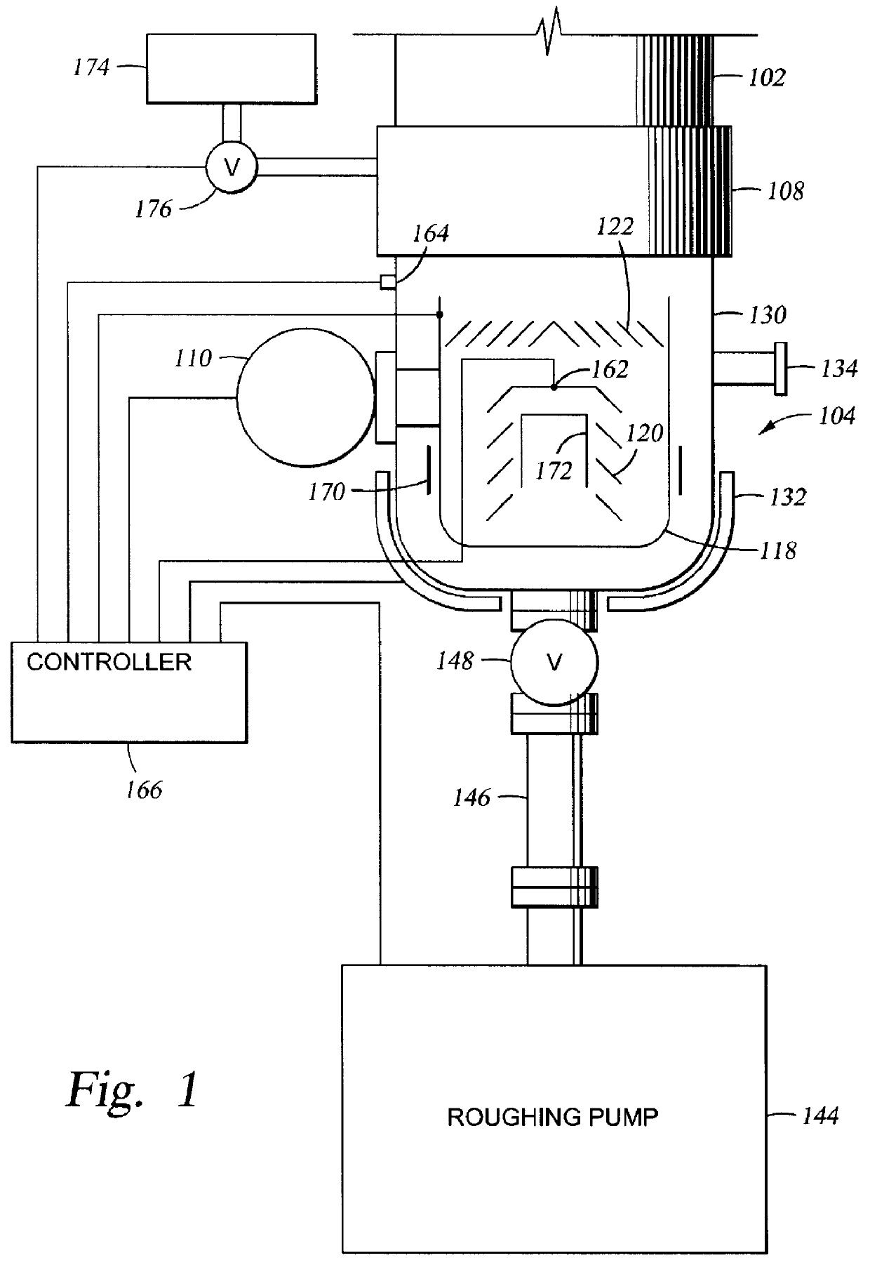
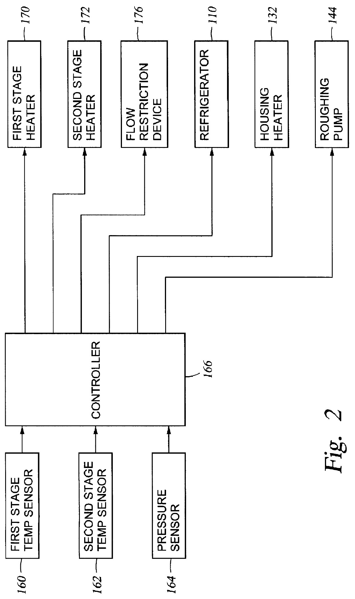
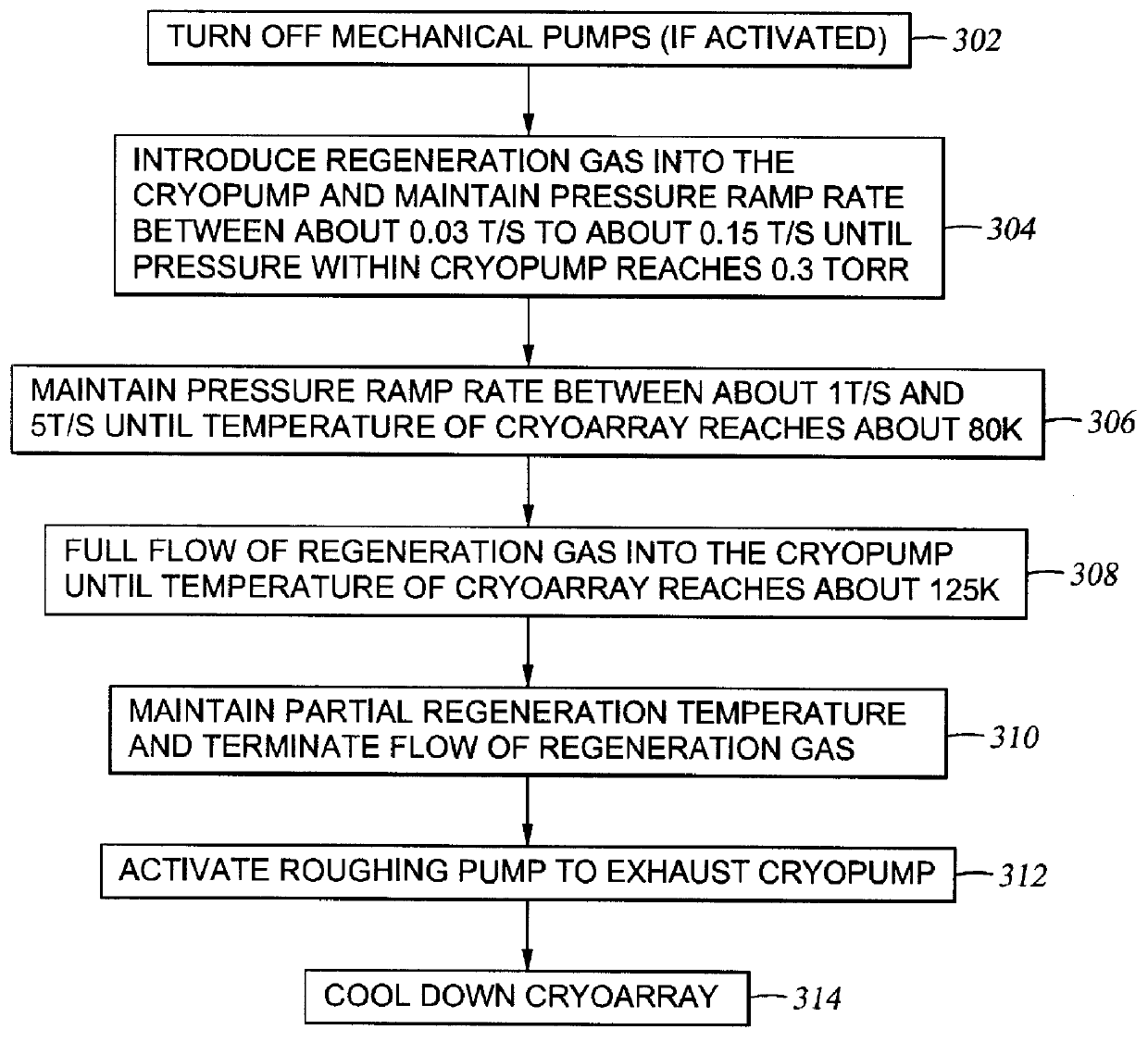
FIG. 3 is a flow chart of a partial regeneration cycle incorporating the "soft start" according to the present invention. As an initial step of the partial regeneration cycle, the roughing pump 144 is turned off (step 302), if it has been in operation during the normal operating cycle. Optionally, the housing heater 132 is activated during the partial regeneration cycle to prevent the housing 130 from reaching low temperatures during the partial regeneration cycle, and thereby prevents condensation of large amounts of water vapor on the outer surface of housing 130.

The partial regeneration cycle is then "soft started" (step 304 and step 306) according to the invention. The "soft start" regeneration is preferably achieved by controlling the flow rate of the regeneration gas into the cryopump used for heating the second stage cryoarray 120. The "soft start" regeneration comprises controlling the pressure ramp rate inside the cryopump during the initial introduction of the regeneration...


PUM

PropertyMeasurementUnit
Temperatureaaaaaaaaaa

Abstract

A method for reducing particulate generation from regeneration of cryogenic vacuum pumps. The method comprises controlling a pressure ramp rate inside the cryopump during an initial introduction of a regeneration gas into the cryopump. Preferably, the pressure ramp rate is controlled by maintaining a first pressure ramp rate, preferably between about 0.03 T/s and 0.15 T/s, until a first pressure of about 0.3 T is reached inside the cryopump and maintaining a second pressure ramp rate between about 1 T/s and 5 T/s until the surface in the cryopump reaches an intermediate temperature between about 40 K and 100 K. Preferably, the temperature ramp rate is also controlled by heating the surface at a temperature ramp rate between about 0.1 K/s and about 0.5 K/s until the intermediate temperature has been reached. Preferably, the temperature ramp rate is controlled by regulating the flow of an inert gas into the cryopump using a flow restriction device. Alternatively, the second stage cryoarray temperature is increased at the rate of between 0.1 K/s and 0.5 K/s using a PID controlled heater.

Description

1. Field of the InventionThe invention generally relates to regeneration of cryogenic vacuum pumps. More particularly, the invention relates to a method for reducing particulate generation from regeneration of cryogenic vacuum pumps.2. Background of the Related ArtCryogenic vacuum pumps (cryopumps) are widely used in high vacuum applications. Cryopumps are based on the principle of removing gases from a vacuum chamber by binding the gases on cold surfaces inside the cryopump. Cryocondensation and cryosorption are the main mechanisms involved in the operation of the cryopump. In cryocondensation, gas molecules are condensed on previously condensed gas molecules, and thick layers of condensation can be formed, thereby, pumping large quantities of gas. Cryosorption is commonly used to pump gases that are difficult to condense at the normal operating temperatures of the cryopump. In this case, a sorbent material, such as activated charcoal, is attached to the coldest surface in the cryo...

Claims


Application Information

Patent Timeline
IPC IPC(8): F04B37/00F04B37/08
CPCF04B37/085
Inventor MORI, GLEN T.CLAWSON, DANIEL O.
Owner APPLIED MATERIALS INC
Why Eureka
Try Eureka