Process for side lobe suppression and amplitude or phase monopulse radar device

a radar device and side lobe technology, applied in the direction of measurement devices, radio wave reradiation/reflection, using reradiation, etc., can solve the problems of supplying erroneous angular measurement data by conventional monopulse radar devices, and affecting the processing of signals of actual targets

Inactive Publication Date: 2000-09-12
SIEMENS SWITZERLAND
View PDF17 Cites 25 Cited by
  • Summary
  • Abstract
  • Description
  • Claims
  • Application Information

AI Technical Summary

Problems solved by technology

In addition, conventional monopulse radar devices supply erroneous angular measurement data as long as the targets cannot be separated distance-wise.
Although the (crossfeed) process described has brought fundamental improvements over the conventional monopulse process, under certain circumstances, measurement errors must also be reckoned with in this process.
In addition, interference signals are often received from the side lobe region sl, which impair the processing of the signals of the actual targets.
In the latter case, the useful part of the signal is also lost.
Due to the requirement for a particular progression of the curvature function, however, limitations arise that counteract an optimization of the curvature process.
In addition to the three antenna functions provided for target measurement (sum, difference, and curvature), curvature monopulse radar devices have up to now required another auxiliary function in order to use the SLS process according to U.S. Pat. No. 4,450,448, which resulted in a higher cost.

Method used


Image

  • Process for side lobe suppression and amplitude or phase monopulse radar device
  • Process for side lobe suppression and amplitude or phase monopulse radar device
  • Process for side lobe suppression and amplitude or phase monopulse radar device

Examples


Embodiment Construction

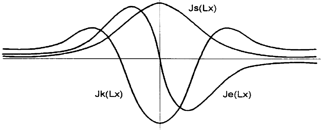
FIG. 2 shows the block circuit diagram of a radar system described in WO 97 / 22890 in which for each measurement axis, three antenna functions, namely a slope function Fe(X), a curvature function Fk(X), and a sum function Fs(X), are provided for the target measurement (X is the target offset angle). The above-mentioned antenna functions Fe(X), Fk(X), and Fs(X) are produced in a known manner by Fourier transformation of the associated illumination functions Je(Lx), Jk(Lx), and Js(Lx) that are depicted in FIG. 3. The functions Fe(X) and Je(Lx), Fk(X) and Jk(Lx), as well as Fs(X) and Js(Lx) are Fourier transformation pairs. Lx is the normalized position on the aperture of the antenna: Lx=2.pi.*lx / .lambda.. The normalization of the actual position lx on the aperture of the antenna takes place by the wavelength .lambda. of the radar signals.

In the process according to the invention, the two functions Fe(X) with regard to Fs(X) and Fk(X) with regard to Fs(X) are now selected so that they c...


PUM


Abstract

The process is used for suppressing the effect of signals that are received or sent via side lobes of an antenna (PA; HA) of an amplitude or phase monopulse radar device, in which for the purpose of position measurement of a first and, if need be, a second target (T1, T2) detected by the radar beam, three illumination functions Je(Lx), Jk(Lx) and Js(Lx) for the antenna (PA; HA) are provided for each measurement axis, as well as antenna functions Fe(X), Fk(X), and Fs(X) resulting from them. The first, second, and third illumination functions Je(Lx); Jk(Lx), and Js(Lx) are selected in this connection so that a quotient function Qe(X)=Fe(X)/Fs(X) or Qk(X)=Fk(X)/Fs(X), which is linearly or quadratically dependent on the target direction, is produced by normalizing the first and the second antenna functions Fe(X); Fk(X) with the third antenna function Fs(X). The power of this quotient is compared with at least one threshold value the or thk that is selected in accordance with the magnitude of the main antenna lobe, and when the threshold value the or thk is exceeded, the effect of the received signal is suppressed. In a preferred embodiment of the invention, the provision is made that the zero points of the antenna functions Fe(X), Fk(X), and Fs(X) are shifted slightly in relation to one another.

Description

1. Field of the InventionThe current invention relates to a method and device for suppressing the effect of signals that are received or sent via side lobes of an antenna of an amplitude or phase monopulse radar device.2. Discussion of Background InformationIn order to locate and if need be, track flying objects, normally monopulse radar devices are used, as have been described, among others, in S. M. Sherman, "Monopulse Princeples and Techniques", Artech House, Norwood 1984. With monopulse radar devices, angular error signals in azimuth and elevation are generated with each received pulse, which become zero when the antenna axis or bore sight axis is aimed precisely at the target. The orientation and if need be tracking of the bore sight axis is executed mechanically in horn antennae. Often in array antennae, the measurement range in elevation is scanned electronically and the measurement range in azimuth is scanned mechanically (see A. E. Acker, "How to Speak Radar", Basic Fundame...

Claims


Application Information

Patent Timeline
Patent Type & Authority Patents(United States)
IPC IPC(8): G01S13/00G01S13/44G01S7/28
CPCG01S7/2813G01S13/44
Inventor KUPFER, HANSPETER
Owner SIEMENS SWITZERLAND
Why Eureka
Try Eureka