Compensation of dispersion

a dispersion and dispersion technology, applied in the field of dispersion compensation, can solve the problems of predetermined value, no system is yet commercially available, and the risk of faulty decision in the receiver exceeds a tolerable valu

Inactive Publication Date: 2000-09-19
TELEFON AB LM ERICSSON (PUBL)
View PDF14 Cites 24 Cited by
  • Summary
  • Abstract
  • Description
  • Claims
  • Application Information

AI Technical Summary

Problems solved by technology

This inter-symbol interference contributes to that the signal cannot be transmitted as long distances as would be liked without that the risk for faulty decisions in the receive

Method used


Image

  • Compensation of dispersion
  • Compensation of dispersion
  • Compensation of dispersion

Examples


Embodiment Construction

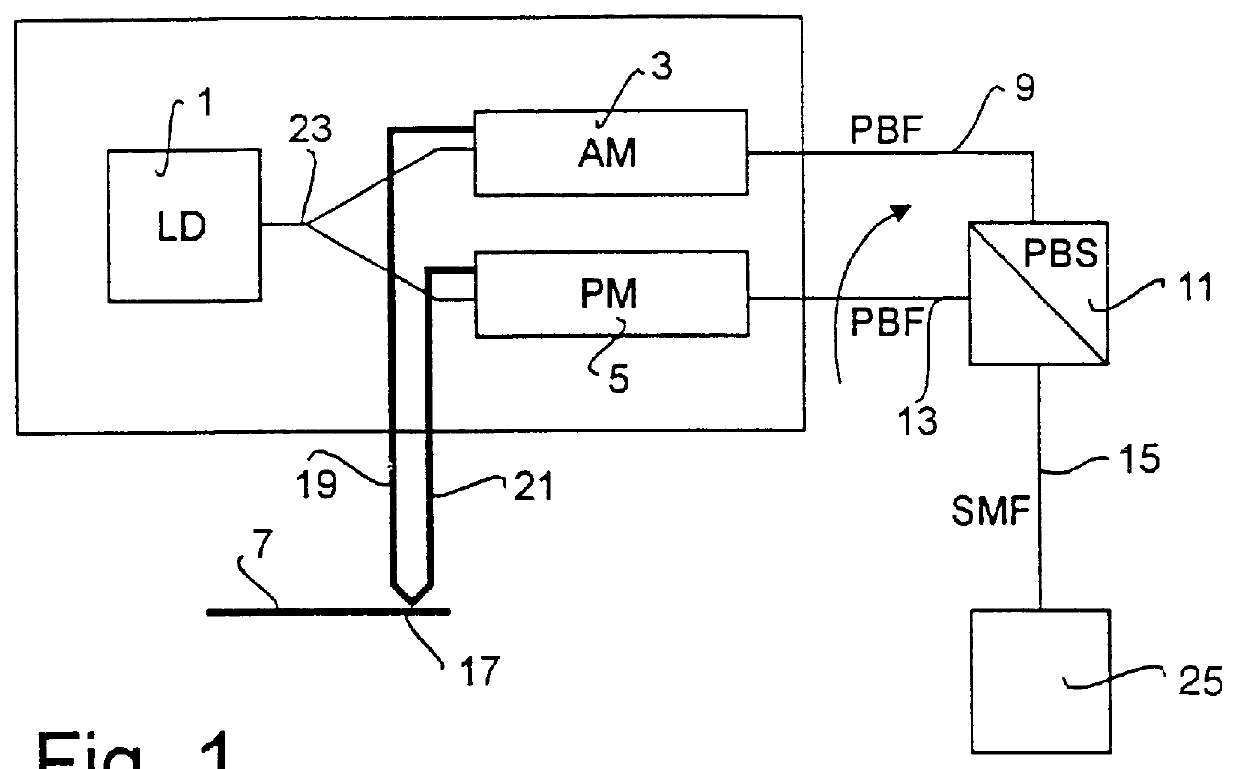
In FIG. 1 a transmitter which is intended to be used for transmitting signals is shown. The transmitter in this embodiment comprises a laser 1, which emits a light beam having a fixed frequency and amplitude. This beam is split into two parallel beams in a beam splitter 23. From the beam splitter 23 the two beams are guided to an amplitude modulator 3 and a phase modulator 5, respectively.

The two modulators 3 and 5 are modulated in parallel with an electrical signal, which is present on a line 7, carrying the information signal, and which is to be transmitted. This signal on the line 7 is split at 17 and transmitted to the amplitude modulator 3 and the phase modulator 5, on the lines 19 and 21, respectively. The output signal from the amplitude modulator 3 passes via a polarization preserving optical fibre 9 to one side of a polarization beam splitter 11, which here acts as a beam collector. The polarized output signal from the phase modulator 5 is transmitted to the polarization be...


PUM


Abstract

In transmission of optical signals in a dispersive medium, the signals are transmitted simultaneously in two modes in an optical fiber (15), which are orthogonal to each other, one of the signals being a non-chirped amplitude modulated signal modulated by an amplitude modulator (3), and the other signal is a phase modulated signal modulated by a phase modulator (5). The received signal is formed by the sum of the amplitude modulated contributions of the two signals. In an optical fiber system, two orthogonal modes of polarization in the same fiber can be chosen. In this manner it will be possible to transmit high bit rates and primarily over long distances.

Description

The invention relates to a method and devices for transmission of optical signals in dispersive medias, e.g. optical fibres.PRIOR ARTIn transmission of data in a dispersive medium, symbols which are transmitted will be distorted at high data rates. That is, the transmitted symbol will be effected by the medium through which it is transmitted, in such a manner that its duration in time will be extended. This results in that, at high data rates, a transmitted symbol is effected both by previously and subsequently transmitted symbols. This inter-symbol interference contributes to that the signal cannot be transmitted as long distances as would be liked without that the risk for faulty decisions in the receiver exceeds a tolerated, predetermined value.Thus, there is a need to try to minimize the distortion which is imposed on the signal when it is transmitted in a dispersive media in order to extend the distance which the signal can be transmitted, or the distance at which the signal mu...

Claims


Application Information

Patent Timeline
IPC IPC(8): H04B10/04G02B6/34H04B3/04G02F1/01H04B10/2507H04B10/2513
CPCG02B6/29394H04B10/25137H04B10/2572H04B10/2507
Inventor DJUPSJOBACKA, ANDERS
Owner TELEFON AB LM ERICSSON (PUBL)
Why Eureka
Try Eureka