Pressure relief valve with pneumatic pilot

a technology of pressure relief valve and pilot, which is applied in the direction of valve operating means/release devices, machines/engines, positive displacement liquid engines, etc., can solve the problems of affecting the operation of the compressor motor. , to achieve the effect of relieving the pressure on the spring and low cos

Inactive Publication Date: 2000-09-26
WESTINGHOUSE AIR BRAKE CO
View PDF3 Cites 6 Cited by
  • Summary
  • Abstract
  • Description
  • Claims
  • Application Information

AI Technical Summary

Benefits of technology

Another object of the present invention is to provide a simple, low cost relief valve that provides such rapid intercooler exhausting while retaining the normal pressure relief function of the valve.
When a compressor is to be unloaded for stating purposes, a pneumatic signal is employed to order such unloading under the auspices of a governor. In the present invention, this signal is also used to open the relief valve by moving the auxiliary piston in a manner that relieves pressure on the spring. This allows the valve member in the relief valve to move immediately past the exhaust ports provided in the valve housing to vent to atmosphere the air received for the intercooler.
The valve device of the invention is a simple, low cost means of packaging a relief or blowdown valve for use in the above discussed compressor / intercooler of U.S. Pat. No. 5,106,270 to Goettel et al. or with single intercooler designs. The valve of the invention can be a completely new and original structure, using all new components, or it can use existing intercooler relief valves by adding an end cap containing the auxiliary piston and a small port for receiving the pneumatic (pilot) signal.

Problems solved by technology

When diesel engine RPM is low, such as in an idle condition, the alternator produces only a limited amount of electrical power.
Such a limited amount of power may be insufficient to operate the compressor motor at a speed sufficient for the compressor to deliver the required amount of compressed air.
When a compressor is unloaded, it rotates freely and thus places a very light load on the motor driving the compressor.
If the motor is required to start or transition against a pressure load in the compressor, the rotor of the compressor can appear to the motor to be locked, and can thereby burn out the motor, as the motor draws large amounts of current to overcome the force of compression in the compressor.
It is therefore understandable that with air pressure in the cylinders acting against the pistons and thus against the crankshaft of the compressor, the drive motor of the compressor has a difficult task in rotating the crankshaft.

Method used


Image

  • Pressure relief valve with pneumatic pilot
  • Pressure relief valve with pneumatic pilot
  • Pressure relief valve with pneumatic pilot

Examples


Embodiment Construction

Prior to proceeding to the much more detailed description of the present invention, it should be noted that identical components which have identical functions have been identified with identical reference numerals throughout the several views illustrated in the drawing figures for the sake of clarity and understanding of the invention.

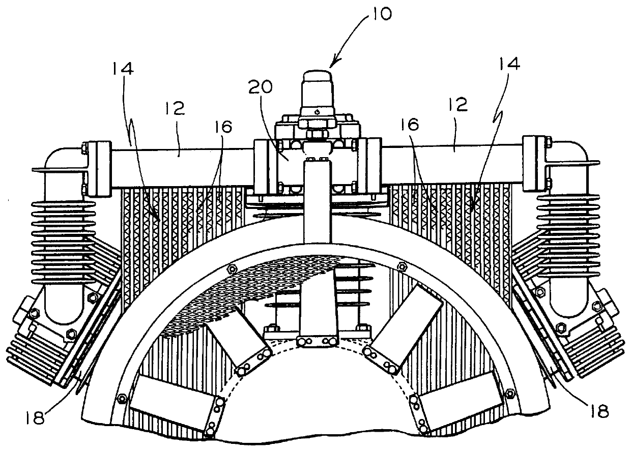
Referring now to FIG. 1 of the drawing, a relief valve 10 of the invention is shown pneumatically connected to two manifolds 12 of two respective intercoolers 14 of a compressor / intercooler combination (depicted as partial view), i.e. the manifolds connect valve 10 to cooling tubes 16 of the intercoolers and to respective, low pressure cylinders 18 of a compressor, not otherwise visible in FIG. 1. A pipe fitting 20 connects the inner ends of the manifolds together and to the valve, the valve being threaded into an upwardly facing opening (not visible) provided in fitting 20.

Pipe fitting 20 also pneumatically connects valve 10 and intercoolers 14 to a ...


PUM


Abstract

A pressure relief valve for rapidly exhausting air pressure from a source of such pressure. The valve includes a housing containing a valve member located across a main port provided in the housing that directly receives the air pressure from the pressure source. A second port is provided for receiving a pilot pressure from the pressure source, and a piston is located adjacent the second port. At least one exhaust port is provided in the housing for exhausting to atmosphere the air received through the main port and against the valve member.

Description

The present invention relates generally to a valve structure for rapidly exhausting air and, more particularly, this invention relates to a valve for the rapid release of air pressure in an intercooler connected to receive compressed air from an air compressor.U.S. Pat. No. 5,106,270 to Goettel et al discloses an air compressor comprised of two low pressure cylinders each of which discharges low pressure air into respective intercoolers to cool such compressed air before it enters a common manifold connection and inlet flange of a high pressure cylinder of the compressor. A single intercooler core design is also available that collectively receives the air discharged from low pressure cylinder heads and, again, cools the air before entering the high pressure head for second stage compression.The compressor can be driven by an electric motor, as disclosed in the Goettel et al patent, though in times past, compressors in locomotives were driven directly by the diesel engine of the loc...

Claims


Application Information

Patent Timeline
Patent Type & Authority Patents(United States)
IPC IPC(8): F16K17/04F16K31/122F16K17/30
CPCF16K17/04
Inventor SANTORO, JR., RALPHCUNKELMAN, BRIAN L.
Owner WESTINGHOUSE AIR BRAKE CO
Why Eureka
Try Eureka