Device for processing road data or intersection data
- Summary
- Abstract
- Description
- Claims
- Application Information
AI Technical Summary
Benefits of technology
Problems solved by technology
Method used
Image
Examples
first embodiment
20. First Embodiment of a Routine for Deleting Locus Data
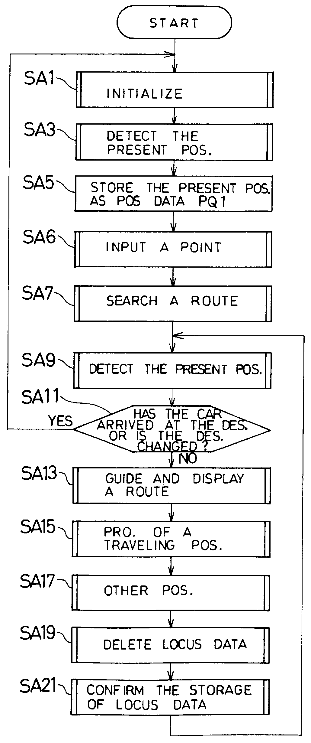
FIG. 26 is a flow chart of the processing for deleting locus data (step SA19) of FIG. 9. First, there is calculated the amount of new locus data to be stored in the locus data storage unit 40. In this case, the second RAM 6 temporarily stores the new locus data that are to be stored, and the amount of the stored data is measured to thereby measure the amount of new data.
Based on the result of measurement, it is determined whether or not the new locus data can be stored in the free memory region of the locus data storage unit 40 (step SK3). That is, it is determined whether the newly formed locus data or the locus data that increase accompanying the updating of the locus data can be all stored in the locus data storage unit 40.
Here, when the free memory region is not sufficient for storing new locus data in the locus data storage unit 40, a predetermined value is unconditionally substituted for the threshold value ZZ (step SK7)...
second embodiment
21. Second Embodiment of a Routine for Deleting Locus Data
FIG. 27 is a flow chart of a second embodiment of the processing for deleting locus data (step SA19) of FIG. 9. In the second embodiment, the locus data are forcibly deleted by the user. First, when an instruction for deleting locus data of locus data storage unit 40 is input to the navigation device through a touch switch 34 (step SK31), a value that is adapted to a routine for forcible deletion is substituted for the threshold value ZZ. The threshold value ZZ used here is different from the threshold value ZZ used in the first embodiment. The link data 60 stored in the locus data storage unit 40 are rearranged in the order of from the oldest traveled date-and-hour data SND to the latest traveled date-and-hour date SND (step SK35).
Furthermore, the evaluated value KCS (SND) is found based upon the traveled date-and-hour data SND, number of times ESK of running and the number of times SEK of running of the links (step SK37). I...
third embodiment
22. Third Embodiment of Deletion of Locus Data
FIG. 28 is a flow chart of a third embodiment of the deleting of locus data (step SA19) of FIG. 9. In the deleting of locus data of the third embodiment, whether or not the locus data is to be stored in the locus data storage unit 40 is determined depending upon the geographical position of the locus data. Whether the locus data should or should not be input to the locus data storage unit 40 is determined depending upon whether one node of the link of the locus data lies within a range of a radius RP(Pn) with the point PT(Pn) as a center.
First, the amount of locus data temporarily stored in the second RAM 6 is measured (step SR1). The amount of data is compared with the free memory capacity of the locus data storage unit 40 (step SR3). When the free memory capacity of the locus data storage unit 40 is not sufficient for the amount of data in the second RAM 6, or when the user instructs start of the processing for deleting the locus data ...
PUM
 Abstract
Description
Claims
Application Information
 - R&D
- Intellectual Property
- Life Sciences
- Materials
- Tech Scout
- Unparalleled Data Quality
- Higher Quality Content
- 60% Fewer Hallucinations
Browse by: Latest US Patents, China's latest patents, Technical Efficacy Thesaurus, Application Domain, Technology Topic, Popular Technical Reports.
© 2025 PatSnap. All rights reserved.Legal|Privacy policy|Modern Slavery Act Transparency Statement|Sitemap|About US| Contact US: help@patsnap.com


