Method and apparatus for rejecting rain clutter in a radar system

a radar system and clutter technology, applied in the field of radar systems, can solve problems such as failure of operators, difficulty in observing obstacles or other, and plague automotive vehicle operators

Inactive Publication Date: 2000-10-03
BENDIX COMML VEHICLE SYST LLC
View PDF6 Cites 66 Cited by
  • Summary
  • Abstract
  • Description
  • Claims
  • Application Information

AI Technical Summary

Benefits of technology

Once the range of a target is determined, the present invention rejects targets that are not within a predetermined detection zone for a selected duration. In accordance with the present invention, the radar system indicates that a target is detected if any part of the target is within the detection zone and it: (1) remains in front of the antenna for at least TH1 seconds; (2) is at a range between Range.sub.min and Range.sub.max ; and (3) is moving faster than Closing-Speed.sub.min relative to the antenna. In one preferred embodiment, the Range.sub.min and Range.sub.max values comprise two and twelve feet, respectively. By rejecting targets that are closer than two feet to the antenna false alarms due to rain clutter are dramatically reduced. Also, by rejecting targets that are further than twelve feet from the antenna the radar system reduces false alarms caused by wet foliage and other wet "non-road" surroundings. In addition, by rejecting targets that are further than twelve feet from the antenna the radar system will not alarm when targets are more than one lane away from the host vehicle and therefore do not pose collision threats to the host vehicle. Moreover, by orienting a square NXN patch array antenna into a diamond-shape configuration, a natural linear amplitude taper is effectively created that aids in rejecting clutter caused by wet road surfaces.

Problems solved by technology

A problem that continues to plague automotive vehicle operators is difficulty in observing obstacles or other vehicles proximate the operators' vehicle but in locations or regions that are difficult to observe from the operators' seat within the vehicle.
Failure of an operator to be aware of an object (typically another vehicle) in this right-side blind spot when making a right-hand turn or a right lane change is a source of numerous accidents.
However, disadvantageously, mirrors are less useful at night and under adverse weather conditions.
Some operators find it difficult to properly interpret the image that is presented in such mirrors (such as convex mirrors that are commonly used as right side mirrors).
Further, mirrors tend to reflect the headlights of vehicles approaching from behind and thus blind the driver of the vehicle on which the mirror is fixed.
However, this solution is complex and expensive, requiring a video camera and video monitor.
Further, a video monitor can present a complex image, which, even if undistorted, can be difficult to interpret rapidly under stressful conditions that occur during heavy traffic conditions.
Still further, monitors can be distracting.
Moreover, like mirrors, such camera systems are less useful at night and under adverse weather conditions such as rain, sleet, or snow.
Disadvantageously, such Doppler radar blind spot sensors frequently generate false warnings (i.e., detect false targets) when used in adverse weather conditions, especially when used in the rain.
Disadvantageously, the prior art vehicular radar systems misinterpret rain clutter, wet road surfaces and wet foliage as dangerous target objects.
Consequently, the prior art radar systems falsely warn the driver of the existence of an object in the driver's blind spot.
This can cause the operator of the host vehicle to lose faith in the reliability of the radar system and leave the system ineffective for warning the operator of real threats.
In addition, such indications are distracting and disturbing to the operator.

Method used


Image

  • Method and apparatus for rejecting rain clutter in a radar system
  • Method and apparatus for rejecting rain clutter in a radar system
  • Method and apparatus for rejecting rain clutter in a radar system

Examples


Embodiment Construction

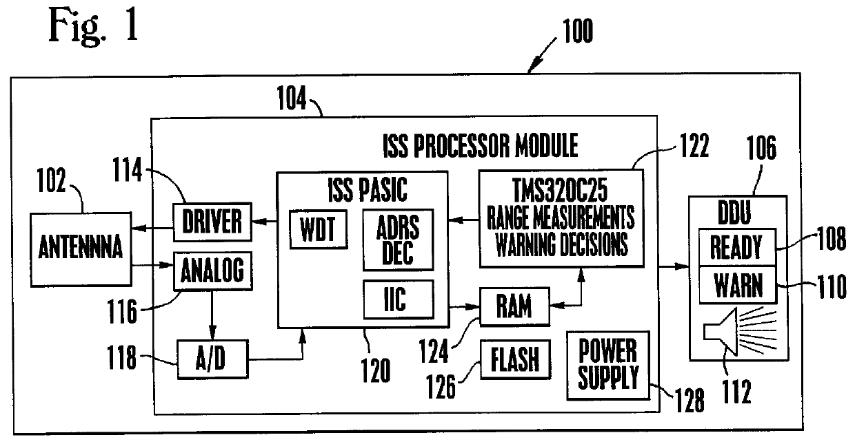
Referring again to FIG. 1, the PM 104 performs many of the important functions of the side-facing radar system 100 of the present invention. For example, the PM 104 generates timing signals to the antenna 102, receives returned analog signals from the antenna 102, conditions the analog signals, and performs an analog-to-digital ("A / D") conversion converting the analog signals into the digital domain. The PM 104 processes the digital antenna data using a PM application specific integrated circuit (ASIC) 120 and a digital signal processor 122 ("DSP"). The PM 104 communicates with the display unit 106 (or, alternatively, with a forward-facing radar system) to indicate alarm and built-in-test ("BIT") failure conditions. The PM 104 also includes non-volatile random access memory ("RAM") and flash RAM circuitry.

As shown in FIG. 1, the PM 104 preferably comprises an antenna driver 114, an antenna receiver 116, an A / D converter 118, the PM ASIC 120, the DSP 122, a RAM 124, a flash RAM 126, ...


PUM


Abstract

A method and apparatus for detecting the presence of objects in a vehicle operator's blind spots. The apparatus comprises a side-facing Doppler radar system using continuous wave (CW) transmission with frequency modulation (FM) operation from a frequency modulation switching technique. The radar system determines the presence, range and closing rate of detected targets. The radar system detects targets even when operated in adverse weather conditions and will not generate false warnings due to rain clutter caused by wet roads and other wet surroundings. The radar system uses ranging techniques to reject false targets that are detected outside of a predetermined target detection zone. In accordance with the present invention, the radar system indicates that a target is detected if and only if any part of the target is within the detection zone and it: (1) remains in front of the antenna for at least TH1 seconds; (2) is at a range between Rangemin and Rangemax; and (3) is moving faster than Closing-Speedmin relative to the antenna. By rejecting targets that are closer than Rangemin feet to the antenna, false alarms due to rain clutter are dramatically reduced. Also, by rejecting targets that are further than Rangemax feet from the antenna, the radar system reduces false alarms caused by wet foliage and other wet "non-road" surroundings. In one embodiment, the radar system uses a patch array antenna oriented into a diamond-shape configuration to effectively create a natural linear amplitude taper that aids in rejecting clutter caused by wet road surfaces.

Description

1. Field of the InventionThis invention relates to radar systems, and more particularly to an apparatus and method for rejecting rain clutter in a radar system used to detect the presence of obstacles in regions that are difficult to see by a host vehicle operator.2. Description of Related ArtA problem that continues to plague automotive vehicle operators is difficulty in observing obstacles or other vehicles proximate the operators' vehicle but in locations or regions that are difficult to observe from the operators' seat within the vehicle. Such locations or regions that are near a vehicle yet not directly observable from the driver's seat are commonly referred to as "blind spots." For example, the region between the angles of 90.degree. and 170.degree., measured with respect to the forward direction of a vehicle in a clockwise direction (i.e., generally to the right of the vehicle and slightly behind the operator's seat), is typically a blind spot, particularly for large vehicles...

Claims


Application Information

Patent Timeline
Patent Type & Authority Patents(United States)
IPC IPC(8): G01S13/00G01S13/93G01S13/34G01S13/32G01S7/02G01S7/41G01S13/06G01S7/295G01S13/931
CPCG01S13/931G01S7/415G01S13/325G01S2013/9385G01S2013/9332G01S13/34G01S2013/93274G01S2013/9315G01S13/06
Inventor MCDADE, JAMES C.STONE, ROBERT E.BOHLEY, ERIC P.SCHLICHTIG, ROGER J.
Owner BENDIX COMML VEHICLE SYST LLC
Why Eureka
Try Eureka