Gas burner with pollution-reducing features

a technology of pollution-reducing features and gas burners, which is applied in the direction of gaseous heating fuel, combustion types, domestic stoves or ranges, etc., can solve the problems of burners affecting the feed rate and burnoff rate of fuel, burners are likely to extinguish completely, and burners are likely to be contaminated

Inactive Publication Date: 2000-10-10
CERAMAT +1
View PDF10 Cites 35 Cited by
  • Summary
  • Abstract
  • Description
  • Claims
  • Application Information

AI Technical Summary

Benefits of technology

The body includes a top vent opening proximate the upper perimeter portion and having a maximum dimension across it. When the burner is ignited, the flames extend from the upper perimeter portion toward the axis and one of the flames has a maximum length. In a highly preferred embodiment, the maximum dimension across the upper perimeter portion is not more than twice the maximum length. In that way, it is substantially assured that byproducts of combustion produced by flames extending from the body lower portion will be subjected to reduction by exposure to very high temperature.

Problems solved by technology

While the burners disclosed in the Ihlenfield et al. and Ahmady patents are presumed to be suitable for their intended purposes, they are not without disadvantages.
A seeming disadvantage of the Ihlenfield et al. burner involves the fuel feed rate and the burnoff rate.
It is understood that this may actually diminish heat output.
And at some even-higher gas feed rate, the burner is likely to extinguish completely.
Another disadvantage of the Ihlenfield et al. burner and, apparently, of that version of the Ahmady burner in which combustion occurs in the plenum is that there is no provision for "afterburning" the products of combustion.
Still another disadvantage of the Ihlenfield et al. and Ahmady burners is that neither is well suited for use with a conventional cooking devices such as a stove top.
A seeming disadvantage of the burner disclosed in the Ahmady patent is its nominal specified gas / air feed rate cannot be exceeded.
There is apparent risk of tube rupture.
Exhaust gas emission may be unduly elevated, particularly with regard to the proportion of carbon monoxide contained in such emission.

Method used


Image

  • Gas burner with pollution-reducing features
  • Gas burner with pollution-reducing features
  • Gas burner with pollution-reducing features

Examples


Embodiment Construction

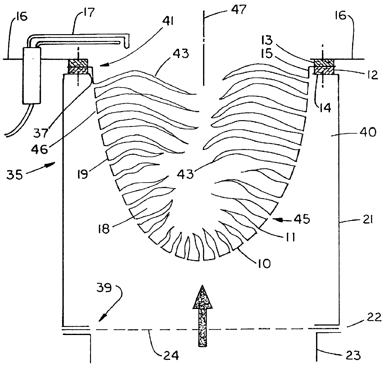
Referring to FIG. 1, the gas burner 35 has a prechamber 21 that forms a housing. The cross sectional shape of the prechamber 21 is not critical and prechambers having at least round or square cross sections are operable. The prechamber 21 has an upper opening 37 and a lower opening 39, the latter surrounded by a flange connection 22, onto which a combustion gas supply line 23 can be attached. An apertured distribution plate 24 is held in a clamped manner between the combustion gas supply line 23 and the prechamber 21. The distribution plate 24 ensures that the combustion gas is uniformly distributed in the prechamber 21 around the gas feed region 40.

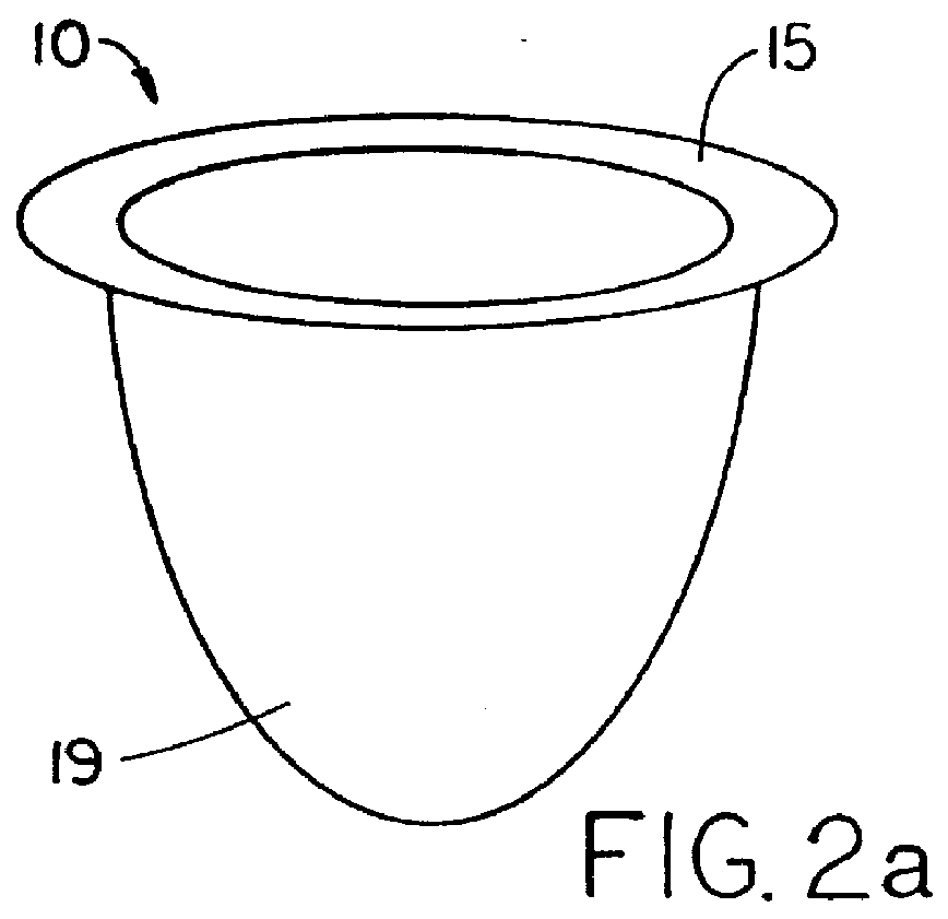
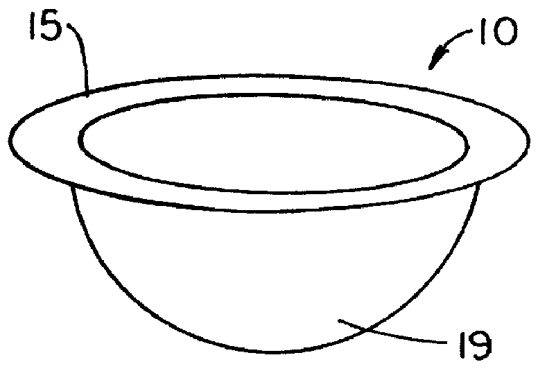
A flange 14 from the prechamber 21 is curved inwardly at a right angle in the area of the upper opening 37 and a gasket 12 is set on the flange 14. The gasket 12 bears the fastening flange 15 of the body 10. Another gasket 13 is set onto the fastening flange 15 and is covered by a fastening plate 16. The fastening plate 16 is screwed to ...


PUM


Abstract

A gas burner has a perforated, hollow body around and defining a combustion chamber. Gaseous fuel is fed to one side of the body, combustion occurs on the other side and the perforations provide a spatial connection between the fuel feed side and the combustion side. The new burner reduces exhaust gas emissions and offers a wide range of performance in the amount of heat energy provided, in the permissible range of gas pressure and in the range of fuels and fuel/air mixtures that can be used with it.

Description

CLAIM OF PRIORITYThis application claims priority from German application DE 196 48 808.7-13 filed in Germany on Nov. 26, 1996.This invention relates generally to combustion and, more particularly, to gaseous fuel combustion using a porous flamehandler.Gas burners, in wide use for decades, are fueled by combustible gases with or without being mixed with air. Very commonly used combustible gases includes natural gas and liquefied propane (LP) gas. (Liquefied propane is stored under pressure in liquid form and becomes gaseous when fed to a gas burner at lower pressure.) Gas burners are useful to heat water, heat a room or a building, carry out industrial processes and for many other purposes.Known gas burners include at least two broad configurations. In one, holes are formed in a sheet metal or cast body and define a straight line, a circle or some other shape. U.S. Pat. No. 5,406,703 (Haen et al.) discloses a burner of this type. In such configuration, holes constitute a relatively ...

Claims


Application Information

Patent Timeline
Patent Type & Authority Patents(United States)
IPC IPC(8): F23D14/02F23D14/00F23D14/48F23D14/20F23D14/58F23D14/14
CPCF23D14/02F23D14/20F23D14/58F23D2203/1015F23D2900/14001F23D2203/106F23D2212/103F23D2212/201F23D2900/00003F23D2203/1023F24C3/047
Inventor KAHLKE, MICHAELROELFSEMA, KLAAS W.SCHEIDLER, HERWIG
Owner CERAMAT
Why Eureka
Try Eureka