SAS fitting for tube and pipe connections

a technology for connecting pipes and fittings, which is applied in the direction of hose connections, sleeves/socket joints, pipe joints, etc., can solve the problems of swage or locking mechanism to "back off" the coupling body, and leak-tight seals may be broken

Inactive Publication Date: 2000-10-17
LOKRING TECHNOLOGY
View PDF10 Cites 116 Cited by
  • Summary
  • Abstract
  • Description
  • Claims
  • Application Information

AI Technical Summary

Benefits of technology

It is, therefore, one of the primary objects of the present invention to provide a mechanism for connecting tubes or pipes which will prevent the mechanism from loosening or backing out when the tube or the fitting is bent, pulled or stressed.
Another object of the present invention is to provide a mechanism for connecting tubes or pipes which will make the manufacturing process easier and thus reduce costs.
Still another object of the present invention is to provide a mechanism for connecting tubes or pipes which will provide a better locking arrangement.

Problems solved by technology

However, usage and bending of the tubing may cause the swage or locking mechanism to "back off" the coupling body and the leak-tight seal may be broken.

Method used


Image

  • SAS fitting for tube and pipe connections
  • SAS fitting for tube and pipe connections
  • SAS fitting for tube and pipe connections

Examples


Embodiment Construction

Prior to proceeding to the more detailed description of the present invention, it should be noted that for the sake of clarity in understanding the invention, identical components with identical functions have been designated with identical reference numerals throughout the drawing Figures.

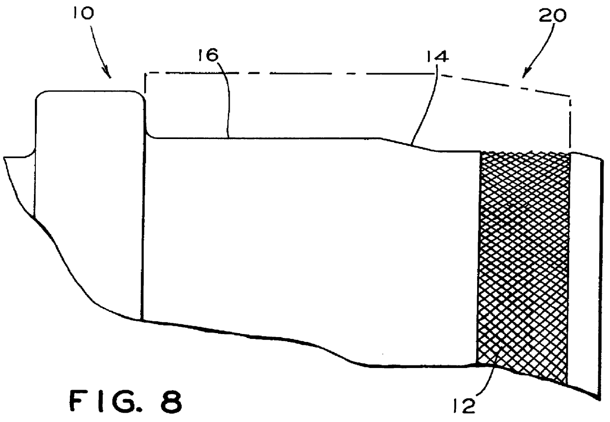
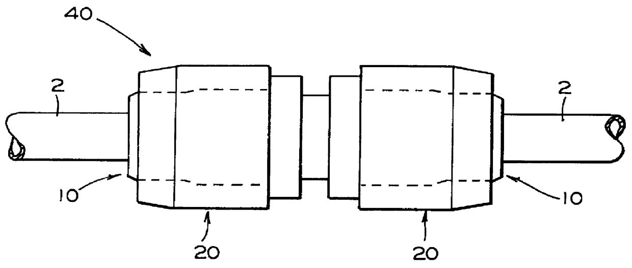
Reference is now made more specifically to FIG. 1. Illustrated therein is a plan view of an embodiment of the invention showing the complete coupling apparatus, generally designated 40. The apparatus 40 includes a driver, generally designated 20, and a coupling body, generally designated 10, which has a hollow interior to allow tube section 2 to easily slide therein initially.

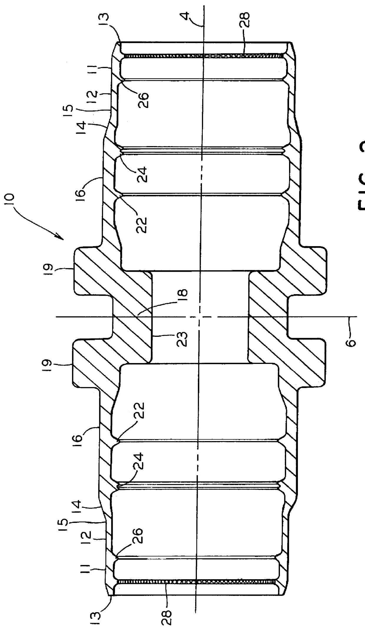
Reference is now made to FIG. 2. Illustrated therein is a partial cross sectional view of coupling mechanism 10, for coupling two sections of tubing 2 together. Tube 2 or tubing as used herein is meant to include tubes, pipe or other conduits. All of these will be collectively referred to as tubes hereinafter.

Such coupling me...


PUM


Abstract

The present invention provides an apparatus for making a tube connection. The apparatus comprises a sleeve having an interior surface adapted for receiving a tube section therein. The sleeve further has an exterior surface having a locking mechanism disposed on an outer portion thereon, such outer portion has a first end and a second end. There is an upwardly inclined surface extending from such second end of such outer portion of the sleeve. Extending inwardly from the upwardly inclined surface is a generally cylindrical sleeve wall that is substantially parallel to a longitudinal axis extending through the sleeve from one end to another. There is further a stop flange disposed on a center portion of such sleeve extending radially outwardly from such center portion of such sleeve, such stop flange is disposed substantially adjacent such generally cylindrical sleeve wall. Such apparatus further includes a driver mechanism for engaging and deforming the sleeve and concurrently such tube section engaged within the sleeve. The driver mechanism has at least two cylindrical sections for engaging the exterior surface of the sleeve. A first end of the driver contacts such stop flange of the center portion of the sleeve and a second end engages the locking mechanism of the outer portion of the sleeve. Such sleeve also includes an anti-torque surface treatment on the inner surface of the ends to resist torsion of the tube.

Description

The present invention is related, in general, to an apparatus which allows pipes or tubes to be joined and sealed together with a mechanical fitting and, more particularly, the present invention relates to a connector having no reverse taper.There are a variety of mechanical fittings currently available to provide for coupling two sections of pipes or tubes together and providing a leak-tight seal. Prior to the introduction of these mechanical devices the majority of these connections were made by welding, soldering or braising the ends of these pipe or tubing sections together. Needless to say the advent of these mechanical fittings reduced the time and cost of joining tubes together.Most of these devices provide for a sleeve or a coupling body which hold the tube or pipe therein and a swage ring or driver that slides over and deforms the sleeve so as to provide a mechanical seal between the sleeve and the tubing.However, usage and bending of the tubing may cause the swage or locki...

Claims


Application Information

Patent Timeline
Patent Type & Authority Patents(United States)
IPC IPC(8): F16L19/00F16L13/14F16L19/04F16L31/00F16L33/22
CPCF16L13/146
Inventor SARESHWALA, SOHEL A.
Owner LOKRING TECHNOLOGY
Why Eureka
Try Eureka