Automatic sheet feeding mechanism

a feeding mechanism and automatic technology, applied in the direction of medical preparations, thin material processing, article separation, etc., can solve the problems of skewing, uneven print quality or jamming of paper within the printer, and printing to appear crooked,

Inactive Publication Date: 2000-10-24
HEWLETT PACKARD DEV CO LP
View PDF29 Cites 30 Cited by
  • Summary
  • Abstract
  • Description
  • Claims
  • Application Information

AI Technical Summary

Problems solved by technology

Even a small amount of skew between the paper and print will cause the printing to appear crooked.
Larger amounts of skew may cause buckling of the paper, resulting in uneven print quality or jamming of the paper within the printer.
The skew is generally induced when the paper is loaded into and/or picked from a stack of paper in a supply tray.
This technique requires a large, flat surface in the area of the roller assembly and is relatively slow.
Still other devices have no skew correction mechanism at all, relying entirely on the accurate feeding of pape

Method used


Image

  • Automatic sheet feeding mechanism
  • Automatic sheet feeding mechanism
  • Automatic sheet feeding mechanism

Examples


first embodiment

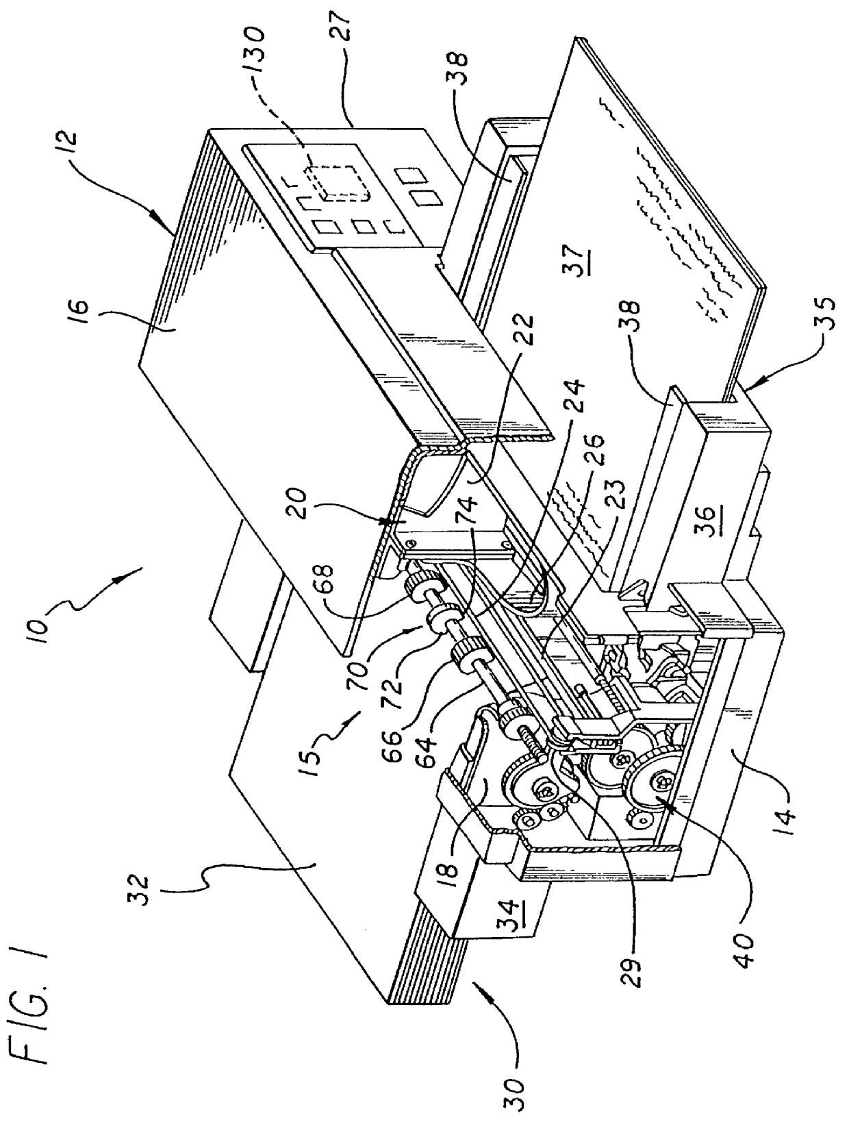
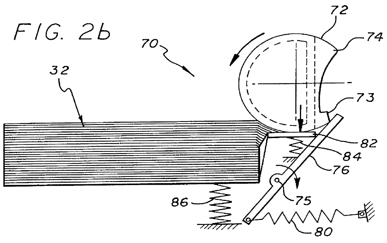
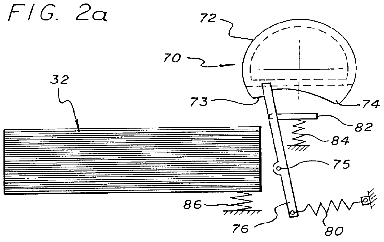
As shown in FIGS. 1-3, in the first embodiment, the kicker mechanism 70 includes a kicker cam 72 mounted on a pick shaft 64 between the first and second pick tires 66 and 68 respectively. As illustrated in the side views of FIGS. 2a-2d, the kicker cam 72 has a crescent-like, semi-circular D-shape. The kicker cam 72 may be made of plastic or other suitable material. The cam 72 has a protrusion 73 at a first end of a can surface adapted to engage a kicker 76. The cam surface has a generally arcuate shape to a second end 74. As discussed more fully below, the arcuate shape of the cam surface facilitates an un-impeded return of the kicker 76 to its home position when the kicker cam 72 has rotated to a position at which the kicker 76 is no longer in contact therewith, i.e., at the second end of the cam surface 74.

In the illustrative implementation, the kicker 76 is a piece of plastic of a substantially planar construction. At the proximal end thereof, the kicker is generally U-shaped wit...

second embodiment

While the embodiment of FIG. 2a is particularly well suited for horizontal stacks of media, FIGS. 4 and 5 is designed for use with an inclined stack of media. The reason for inclining the stack 32 is to reduce the footprint of the printer 10. However, when the stack is inclined, many more sheets remain on the separator pad 82 due to the force of gravity. Unfortunately, it is difficult to engineer a kicker spring 80 that is strong enough to clear the sheets from the separator pad 82 without causing damage to same.

FIG. 4 is a perspective view of a printer incorporating the second illustrative embodiment of the sheet feeding mechanism of the present invention with the housing thereof partially removed. Note that the mechanism is essentially identical to that of FIG. 1 with the exception that the supply tray 34 is inclined relative to the housing assembly 12 and the kicker mechanism 70' differs from the kicker mechanism 70 of FIG. 1 as discussed more fully below.

FIGS. 5a-5f provide simp...

third embodiment

The operation of the third embodiment is best illustrated with respect to FIGS. 6a-6d. FIG. 6a shows the mechanism 70" in its home position and initialized. The pick tires 66 and 68 and the separator roll 72" are rotated exactly one revolution per pick cycle. The paper stack is raised and presented to the pick tires at the beginning of the cycle and lowered before its completion.

FIG. 6b shows the pick tires 66 and 68 rotating counter-clockwise and pulling the top few sheets from the raised stack into the separation zone. At the same time, the separator roll 72" is rotating counter-clockwise which keeps all but the top sheet 33 from getting past the kickers 76" and 77". This causes the flexible kickers 76" and 77" to bend down and out of the way.

FIG. 6c shows the stack 32, which has been lowered and the pick tires 66 and 68 and the separator roll 72" continuing to rotate in the same direction. The flexible kickers 76" and 77" are gent back by the single sheet 33 as it passes thereove...


PUM


Abstract

A sheet feeding mechanism including a pick apparatus for selectively moving a sheet of media from a stack. A kicker is disclosed in several embodiments and serves to retain media on the stack. In a first embodiment, a cam is coupled to the pick apparatus for deflecting the kicker from the first position at which it retains media on the stack to a second position at which paper is allowed to move through the mechanism. In a particular implementation of the first illustrative embodiment, the mechanism includes a frame and a shaft mounted on the frame for rotational movement relative thereto. The pick apparatus includes a pick tire mounted on the shaft and adapted to rotate therewith. The kicker is mounted on the frame for retaining media on the stack in a first position. The cam is adapted to deflect the kicker during a first portion of a rotational cycle and to release the kicker when the cam is in a second rotational position. In a second embodiment, the cam is contoured to provide a protruded edge which engages the kicker when the cam is counter-rotated. This forces the kicker to push media remaining on a separation roll back onto the stack and is particularly well suited for printers utilizing inclined media trays. In a third embodiment, the kicker is mounted on a shaft along with a separation roll. In a specific implementation of this embodiment, the kicker is a flexible strip of plastic that flexes as it engages the stack when the shaft is rotated and after it has rotated around, pushes media remaining on the separation roll back onto the stack. Finally, a fourth embodiment is disclosed by which the kickers are implemented with a plurality of small gravity actuated kickers mounted between two pick tires. The kickers are adapted to fall out of the way when the pick tires are rotating in a first direction and to fall into position to push media back onto the stack when the pick tires are counter-rotated.

Description

1. Field of the InventionThe present invention relates to hard copy media control apparatus. More specifically, the present invention relates to method and apparatus for control of paper in a cut-sheet paper feeding mechanisms for use with printers, plotters, copiers, facsimile machines and the like.2. Description of the Related ArtPaper feed mechanisms for hard copy control apparatus are well known in the art. In automatic cut sheet printers, a stack of paper is automatically fed to a printer, plotter, copier, facsimile machine, or other apparatus typically using a roller assembly or other mechanism. An important function of the feed mechanism is to control the parallelism between the top edge of the sheet of paper and the first line of print contained thereon, i.e., the amount of skew between the paper and the print. Even a small amount of skew between the paper and print will cause the printing to appear crooked. Larger amounts of skew may cause buckling of the paper, resulting i...

Claims


Application Information

Patent Timeline
IPC IPC(8): B65H3/52B65H3/56B65H3/06
CPCB65H3/0638B65H3/5223B65H3/56B65H3/34B65H3/565Y10S271/902B65H2404/121B65H2601/2531
Inventor PADGET, MARTIN JAY
Owner HEWLETT PACKARD DEV CO LP
Why Eureka
Try Eureka