Angle detection method, angle detection apparatus, rotation drive apparatus, robot apparatus, and storage medium

a technology of rotation drive apparatus and angle detection, which is applied in the direction of instruments, manufacturing tools, arms, etc., can solve the problems of encoder detection, not the technology to address the degradation of positioning accuracy, and the difficulty of accurately detecting the rotation angle of the rotation drive apparatus. achieve the effect of high accuracy

Active Publication Date: 2015-10-01
CANON KK
View PDF3 Cites 23 Cited by
  • Summary
  • Abstract
  • Description
  • Claims
  • Application Information

AI Technical Summary

Problems solved by technology

Degradation factors of a positioning accuracy for the tip position of the robot arm include an angle transmission error or a torsion of the reduction gear in the rotation drive apparatus of the robot arm, an encoder detection error, and the like.
This encoder detection error refers to an error derived from a deviation based on an eccentricity when a shaft of the encoder and a rotating disc are mounted with respect to ideal positions.
Therefore, this is effective in the correction of the angle transmission error of the reduction gear in the rotation drive apparatus but is not the technology to address the degradation in the positioning accuracy which is caused because of the encoder detection error.
For that reason, if the encoder detection error caused by the eccentricity between the rotating center of the rotating disc and the shaft occurs in the encoder itself in the first place, it is difficult to detect the accurate rotation angle of the rotation drive apparatus.
Since this encoder detection error exists, even when the technique described in Japanese Patent Laid-Open No. 2012-137310 is used in the device that utilizes the reduction gear such as the robot arm, limitations exist when the control for positioning the output shaft at a high accuracy and the torsional feedback control are performed.
This is because an error amount obtained by multiplying the input shaft encoder detection error by a reduction gear ratio of the reduction gear is generated as the positioning error of the output shaft.
In general, since the encoder involving the small encoder detection error is extremely expensive, it is not necessarily practical to provide the encoder to the input / output shaft of the robot arm.
That is, according to this related art method, the encoder detection error of the encoder arranged in the rotation drive apparatus is not sufficiently taken into account.
For that reason, a problem occurs that it is practically difficult to perform the control for positioning the output shaft at a high accuracy and the torsional feedback control to improve the accuracy for positioning the tip position of the robot arm.

Method used


Image

  • Angle detection method, angle detection apparatus, rotation drive apparatus, robot apparatus, and storage medium
  • Angle detection method, angle detection apparatus, rotation drive apparatus, robot apparatus, and storage medium
  • Angle detection method, angle detection apparatus, rotation drive apparatus, robot apparatus, and storage medium

Examples


first exemplary embodiment

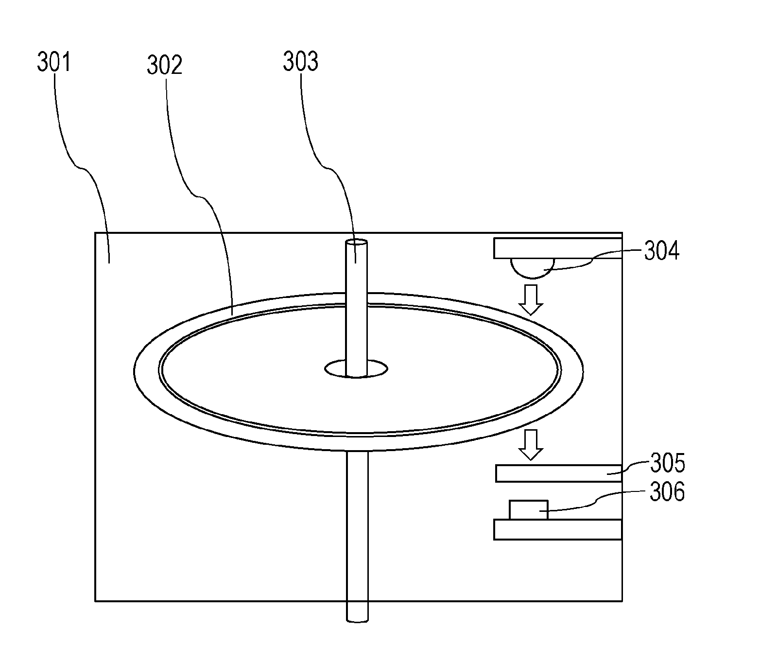
[0056]FIGS. 2A and 2B are drawings that effectively represent characteristics of the present invention. FIG. 2A is a cross sectional view of a rotation drive apparatus provided with an angle detection apparatus according to an exemplary embodiment of the present invention, and FIG. 2B illustrates a signal flow. In FIG. 2A, a motor 203 rotates the input shaft 205 that corresponds to a first rotation shaft. A reduction gear 204 functioning as a power transmission unit performs speed reduction in accordance with the rotation of the input shaft 205 at a previously set reduction gear ratio, for example, 10:1, and rotates the output shaft 206 that corresponds to a second shaft. That is, while the motor 203 rotates the input shaft 205, and the input shaft 205 is rotated, the output shaft 206 is rotated via the reduction gear 204.

[0057]Here, the reduction gear 204 will be described. While a wave generator (WG) 213 configured to generate waves and coupled to the input shaft 205 rotates, a fl...

second exemplary embodiment

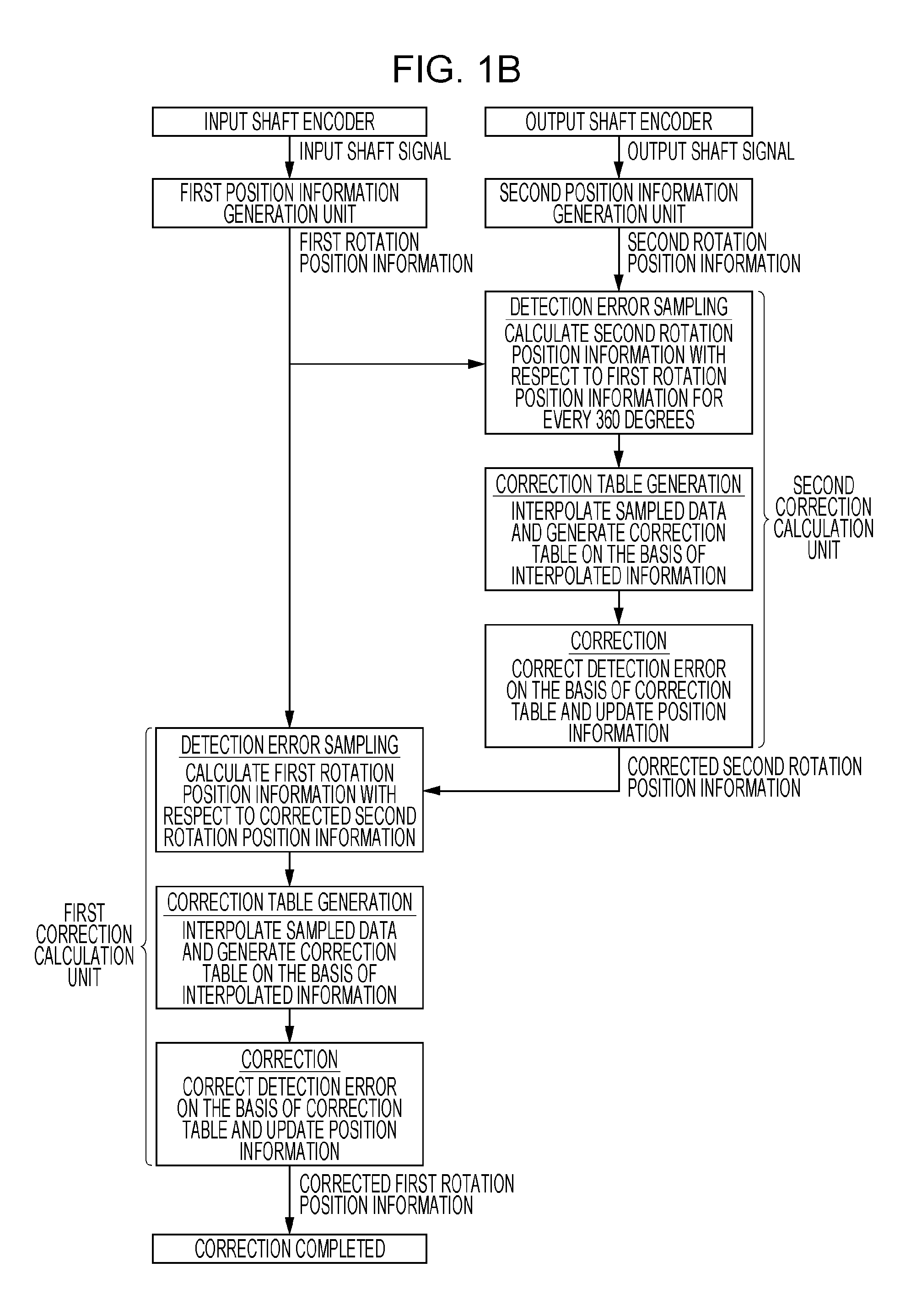
[0077]According to a second exemplary embodiment, descriptions related to configurations similar to the first exemplary embodiment will be omitted, and only configurations different from the first exemplary embodiment will be described. According to the first exemplary embodiment, the descriptions have been given while the rotation position information for every 360 degrees of the input shaft encoder 201 is set as the reference to correct the output shaft encoder detection error. In contrast to this, according to the second exemplary embodiment, descriptions will be given while the rotation position information of the output shaft encoder 202 after the correction is set as the reference to correct an input shaft encoder detection error.

[0078]FIG. 1B is a flow chart illustrating the exchanges of the signals and the information in the angle detection method according to the present exemplary embodiment.

[0079]The first correction calculation unit 210 calculates the first rotation posit...

third exemplary embodiment

[0082]FIG. 16 illustrates a vertical articulated six-axis robot arm. In FIG. 16, first to sixth joints 601 to 606 are coupled to each other by links. FIG. 16 illustrates an example in which the above-described angle detection method is applied to the robot arm. It is however noted that the present invention is not limited to be applied to the vertical articulated six-axis robot. The angle detection apparatus according to the exemplary embodiment of the present invention is provided to at least one of the first to sixth joints 601 to 606 and is configured to detect the rotation angle from the reference angle at each of the joints of the robot arm. The motor and the angle detection apparatus constitute the rotation drive apparatus. A characteristic of the exemplary embodiment of the present invention resides in the robot arm having the joint parts and the joint part of the robot arm which is provided with the rotation drive apparatus.

[0083]In addition, another characteristic of the ex...


PUM


Abstract

To provide an angle detection method with which a control for positioning an output shaft using an input shaft encoder and output shaft encoder at a high accuracy and a torsional feedback control can be realized and an angle detection apparatus that executes the angle detection method. In a robot arm constituted by an input shaft encoder, an output shaft encoder, a motor, a reduction gear, and the like, an output shaft encoder detection error is corrected by setting rotation position information using a periodicity of rotations of the input shaft encoder as a reference. When the input / output shaft encoder detection error is corrected in this manner, the control for positioning the output shaft at a high accuracy and the torsional feedback control can be realized.

Description

BACKGROUND OF THE INVENTION[0001]1. Field of the Invention[0002]The present invention relates to a method of correcting an encoder detection error caused by an eccentricity between a shaft and a rotating disc.[0003]2. Description of the Related Art[0004]Up to now, a robot arm includes a rotation drive apparatus constituted by a servo motor (hereinafter, will be referred to as motor) which is configured to drive an articulating mechanism and a reduction gear configured to obtain a high output torque. The rotation drive apparatus is provided with a rotary encoder (hereinafter, will be referred to as encoder) which is configured to detect an angle of a rotator. The encoder is directly connected to a rotation shaft of the motor and controls a tip position of a robot arm by feeding back information of the rotation angle detected by the encoder to the motor.[0005]In recent years, since demands for an industrial robot that can assembly high-precision parts have been increased, a higher acc...

Claims


Application Information

Patent Timeline
Patent Type & Authority Applications(United States)
IPC IPC(8): G01D5/347H02K11/00B25J9/12G01D5/26
CPCG01D5/34738G01D5/264G01D5/34707Y10S901/46B25J9/126Y10S901/23H02K11/0026B25J13/088G01D5/24485G01D5/2449G01D2205/28H02K11/22Y10T74/20317
Inventor HASEBE, SATOSHINAKAJIMA, YOHJI
Owner CANON KK
Why Eureka
Try Eureka