

Electrode and method of making same
a technology of electrodes and electrodes, applied in the direction of welding/cutting media/materials, manufacturing tools, welding apparatus, etc., can solve the problems of inability to filling or alloying agents, inability to resist moisture contamination and physical damage to fluxing, etc., to reduce the resistance in the narrow, and reduce the cross-sectional area of the wire
- Summary
- Abstract
- Description
- Claims
- Application Information
AI Technical Summary
Benefits of technology
Problems solved by technology
Method used
Image

Examples
Embodiment Construction
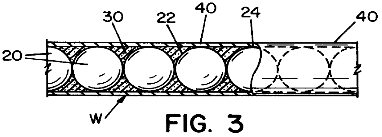
Referring now to the drawings, wherein the showings are for the purpose of illustrating a preferred embodiment of the present invention and not for the purpose of limiting same, FIG. 1 illustrates a welding wire W constructed in accordance with the present invention is shown. This wire has a series of distinct, quantized segments Q which are defined by each spherical metal ball 20. Each narrow region 22 of the quantized segment Q is located between each of the metal balls. The narrow region 22 is positioned inward of cylindrical surface 24 for welding wire W. Cylindrical surface 24 is the surface of metal ball 20 at the maximum diameter a of the metal ball which corresponds to the diameter of wire W. As can be appreciated, quantized segments Q and the narrow region 22 can take a variety of shapes and sizes. The maximum diameter of the quantized segments determines the cylindrical surface 24 of wire W. The narrow region 22 of the quantized segments has a maximum diameter that is less...
PUM
| Property | Measurement | Unit |
|---|---|---|
| outer diameter | aaaaa | aaaaa |
| volume | aaaaa | aaaaa |
| diameter | aaaaa | aaaaa |
Abstract
Description
Claims
Application Information