Stepper motor controller for microstepping a stepper motor and a method for microstepping a stepper motor

a stepper motor and controller technology, applied in the field of stepper motors, can solve the problems of increasing overhead associated with stepper motors in control applications, their characteristic resonance generated, etc., and achieve the effects of reducing the overhead of the overall system processor, reducing the amount of processing capacity, and reducing the resonance of the motor

Inactive Publication Date: 2000-10-31
BRISTOL MYERS SQUIBB CO
View PDF22 Cites 42 Cited by
  • Summary
  • Abstract
  • Description
  • Claims
  • Application Information

AI Technical Summary

Benefits of technology

One aspect of the invention provides a stepper motor control circuit which reduces overhead in an overall system processor by reducing the amount of processing capacity required in issuing control commands when microstepping is used to reduce resonance in the motor. The reduction in overhead in the system processor is accomplished by the control circuit which dynamically interpolates motor positions between steps commanded from the processor, thus allowing greater step resolution without increasing the commands issued from the processor.

Problems solved by technology

One disadvantage to using stepper motors in control applications is their characteristic resonance generated by overshoot and recovery due to step size and positional velocity.
A negative aspect of microstepping is the increased overhead associated with generating pulse trains from the system control circuit to the microstepping controller.
However, while addressing the problem of resonance experienced by the stepper motors, like other known methods, Friedman et al. does so at the expense of large overhead associated with generating pulse trains from the system control circuit to the microstepping controller.
However, while reducing the overhead associated with generating pulses for microstepping the stepper motor by utilizing a look up table, Wright et al. limits the accuracy of the stepper motor to the values stored in the look up table.
Thus, the control system proposed by Wright et al. cannot account for various degrees of microstepping that may be required for precision control of the stepper motor.
Accordingly, when the look up table does not provide sufficient accuracy, the stepper motor utilizing the Wright et al microstepping method will suffer same problem as a stepper motor which is not microstepped i.e., the characteristic resonance generated by overshot and recovery due to step size and positional velocity.

Method used


Image

  • Stepper motor controller for microstepping a stepper motor and a method for microstepping a stepper motor
  • Stepper motor controller for microstepping a stepper motor and a method for microstepping a stepper motor
  • Stepper motor controller for microstepping a stepper motor and a method for microstepping a stepper motor

Examples


Embodiment Construction

A stator and rotor arrangement of a typical stepper motor employing the microcontrol system of the present invention is described below.

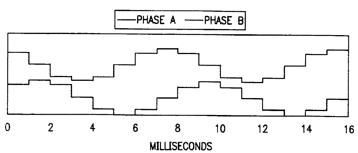
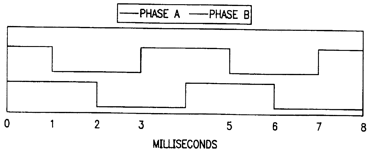
The stators of stepper motors consist of an even number of electromagnets that are formed by energizing internal coils accessible from the motor's control wires. This description shall refer to these electromagnets as teeth or stator teeth. The stator has two sets of teeth. Either two or three wires control each set. We will call one set of wires and teeth phase A and the other set phase B. Current flowing through phase A energizes half of the teeth. Current flowing through phase B energizes the other half of the teeth. The teeth are arranged in a circular pattern such that there is a phase A tooth between each pair of phase B teeth and there is a phase B tooth between each pair of phase A teeth. A tooth that is 180.degree. from another tooth will be controlled by the same phase, but will have the opposite polarity as the other tooth.

The rotors of s...


PUM


Abstract

A low overhead controller for microstepping a stepper motor and a low overhead method for microstepping a stepper motor. The reduction in overhead in system processor is accomplished by the control circuit which dynamically interpolates motor positions between steps commanded from the processor. Also, the reduction in overhead is accomplished by a microstepping method used to effect microstepping resolution control by employing a stored look-up table which gives a resolution value at a given speed according to a predetermined function.

Description

1. FIELD OF THE INVENTIONThe present invention is in the field of stepper motors and, in particular, provides a low overhead controller for microstepping a stepper motor and a low overhead method for microstepping a stepper motor.2. BACKGROUNDStepper motors have significant advantages for systems which require low cost motion control with precise mechanical placement. One disadvantage to using stepper motors in control applications is their characteristic resonance generated by overshoot and recovery due to step size and positional velocity. A common method for overcoming this problem is to "microstep" the motor. Microstepping reduces resonance by decreasing the distance traveled by the rotor between each step. A negative aspect of microstepping is the increased overhead associated with generating pulse trains from the system control circuit to the microstepping controller. Various techniques have been developed for microstepping the stepper motors. For example, U.S. Pat. No. 4,446,...

Claims


Application Information

Patent Timeline
Patent Type & Authority Patents(United States)
IPC IPC(8): H02P8/22
CPCH02P8/22
Inventor CARR, RAYMOND A.JOHNS, MICHAEL R.
Owner BRISTOL MYERS SQUIBB CO
Why Eureka
Try Eureka