Optical membrane forming apparatus and optical device produced by the same

a technology of optical membrane and forming apparatus, which is applied in the direction of instruments, optical elements, vacuum evaporation coating, etc., can solve the problems of large degree of uneven thickness of optical membrane, inability to achieve designed optical properties, and likely deviation of actual distribution of vaporization

Inactive Publication Date: 2000-11-07
NIKON CORP
View PDF16 Cites 33 Cited by
  • Summary
  • Abstract
  • Description
  • Claims
  • Application Information

AI Technical Summary

Problems solved by technology

In addition, the actual distribution of vaporization is likely to deviate from the ideal state depending on the type and shape of the sample to be vaporized, the atmosphere of the vacuum chamber, and the vaporization conditions.
Especially when forming a membrane on an optical device having a curved surface, such as a concave mirror and a convex mirror, the degree of unevenness in the thickness of the optical membrane becomes large.
With a single mask 106, the thickness of each layer of the multi-layer membrane may vary depending on the position on the lens substrate 3, and as a result, the designed optical properties may not be achieved.

Method used


Image

  • Optical membrane forming apparatus and optical device produced by the same
  • Optical membrane forming apparatus and optical device produced by the same
  • Optical membrane forming apparatus and optical device produced by the same

Examples


Embodiment Construction

FIG. 4 is a table of the ratio of the vaporization rates for forming a multi-layer membrane.

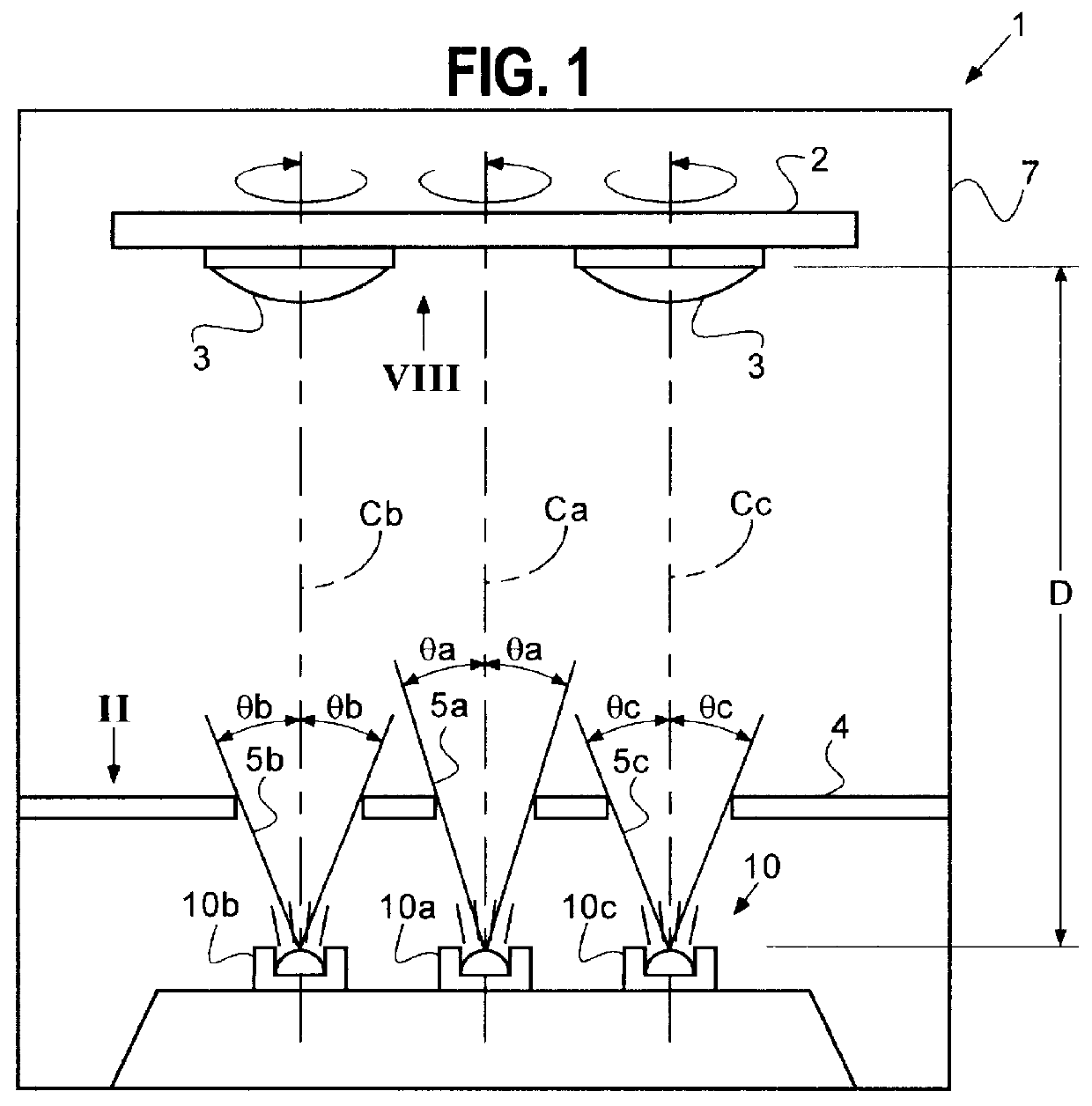
The optical membrane forming apparatus 1 described above is used to form this multi-layer membrane. The ratio of the radius of curvature to the effective diameter of the lens to be coated is 1.4:2. A three-layer anti-reflection membrane (having MgF.sub.2, ZrO.sub.2, and Al.sub.2 O.sub.3 layers in this order from the top) is formed on this lens. The thickness of the three layers are 1 / 4 optical wavelength, 1 / 2 optical wavelength, and 1 / 4 optical wavelength, respectively.

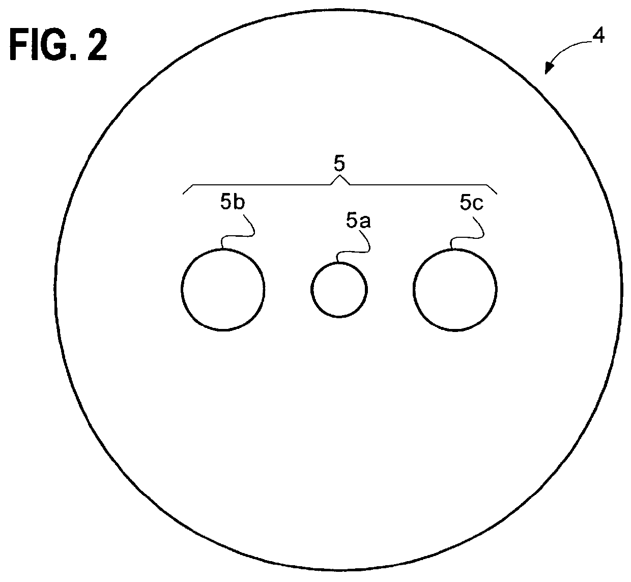
To form this anti-reflection membrane, the distance D from the vaporization plane of the source 10 to the surface of the substrate holder 2, on which lenses 3 are held, is set to 1000 mm. After the sizes of the apertures 5a, 5b and 5c are adjusted, the diaphragm plate 4 is placed between the vaporization sources 10 and the lenses 3 so that the angle .theta.a for the vaporization stream from the first source 10a is 16.degree., a...


PUM

PropertyMeasurementUnit
distanceaaaaaaaaaa
angleaaaaaaaaaa
incident angleaaaaaaaaaa

Abstract

An optical membrane forming apparatus comprises a vacuum chamber (7), a lens holder (2) placed in the chamber (7) for holding one or more lenses (3) in such a manner that each lens (3) is rotational about its axis, and that the lens holder (2) itself is rotational about its own axis, and a plurality of vaporization sources (10a-10c) placed in the chamber (7). Each of the vaporization sources (10a-10c) produces vaporized particles for forming a layer of the membrane on the surface of the lens (3). The vaporization rate of the plurality of vaporization sources are independently controlled. A diaphragm plate (4) is placed between the vaporization sources (10a-10c) and the lenses (3) in order to control the direction of diffusion of the vaporized particles. Each of the sources (10a-10c) has a sample container which is partitioned into a plurality of rooms to store different samples.

Description

1. Field of InventionThis invention relates to an apparatus for forming an optical membrane of a uniform thickness, such as a reflection coating and an antireflection coating, on a curved surface of an optical device (e.g., a lens, a concave or convex mirror).2. Description of the Related ArtWith a conventional optical membrane forming apparatus, the particles vaporized by the vaporization source J are spattered toward the optical device K held above the vaporization source J, and deposited on the surface of the optical device K, as shown in FIG. 6. If the vaporization source J is placed on a plane, the thickness of the membrane formed on the optical device K in the ideal state is defined by equation:t.infin.cos.sup.2 .theta. / d.sup.2 (1)where t is the thickness of the membrane formed on the optical device K, .theta. is the angle between the vertical axis extending upward from the vaporization plane and the spattering direction of the vaporized particle, and d is the distance between...

Claims


Application Information

Patent Timeline
Patent Type & Authority Patents(United States)
IPC IPC(8): C23C14/24G02B1/10C23C14/50C23C14/54G02B1/11G02B1/115
CPCC23C14/24
Inventor TOMOFUJI, TETSUYA
Owner NIKON CORP
Why Eureka
Try Eureka