Apparatus and method of metering and transfer of cryogenic liquids

Inactive Publication Date: 2000-11-07
CRYOGENIC FUELS
View PDF1 Cites 36 Cited by
  • Summary
  • Abstract
  • Description
  • Claims
  • Application Information

AI Technical Summary

Benefits of technology

An object of the present invention is to effect the metering and transfer of cr

Problems solved by technology

Known apparatuses and methods for effecting the transfer of cryogenic liquids require a series of manual operations which require skilled operators, entail substantial time and expense and invite damage to equipment and loss of valuable cryogenic liquids.
Also, due to the extremely cold temperatures of the liquids

Method used


Image

  • Apparatus and method of metering and transfer of cryogenic liquids
  • Apparatus and method of metering and transfer of cryogenic liquids
  • Apparatus and method of metering and transfer of cryogenic liquids

Examples


Embodiment Construction

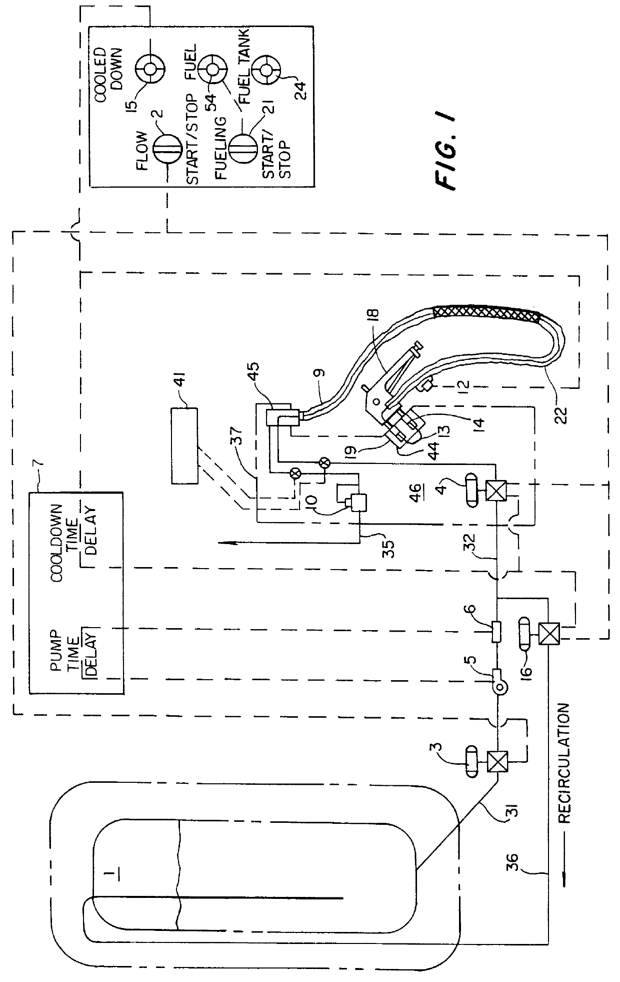
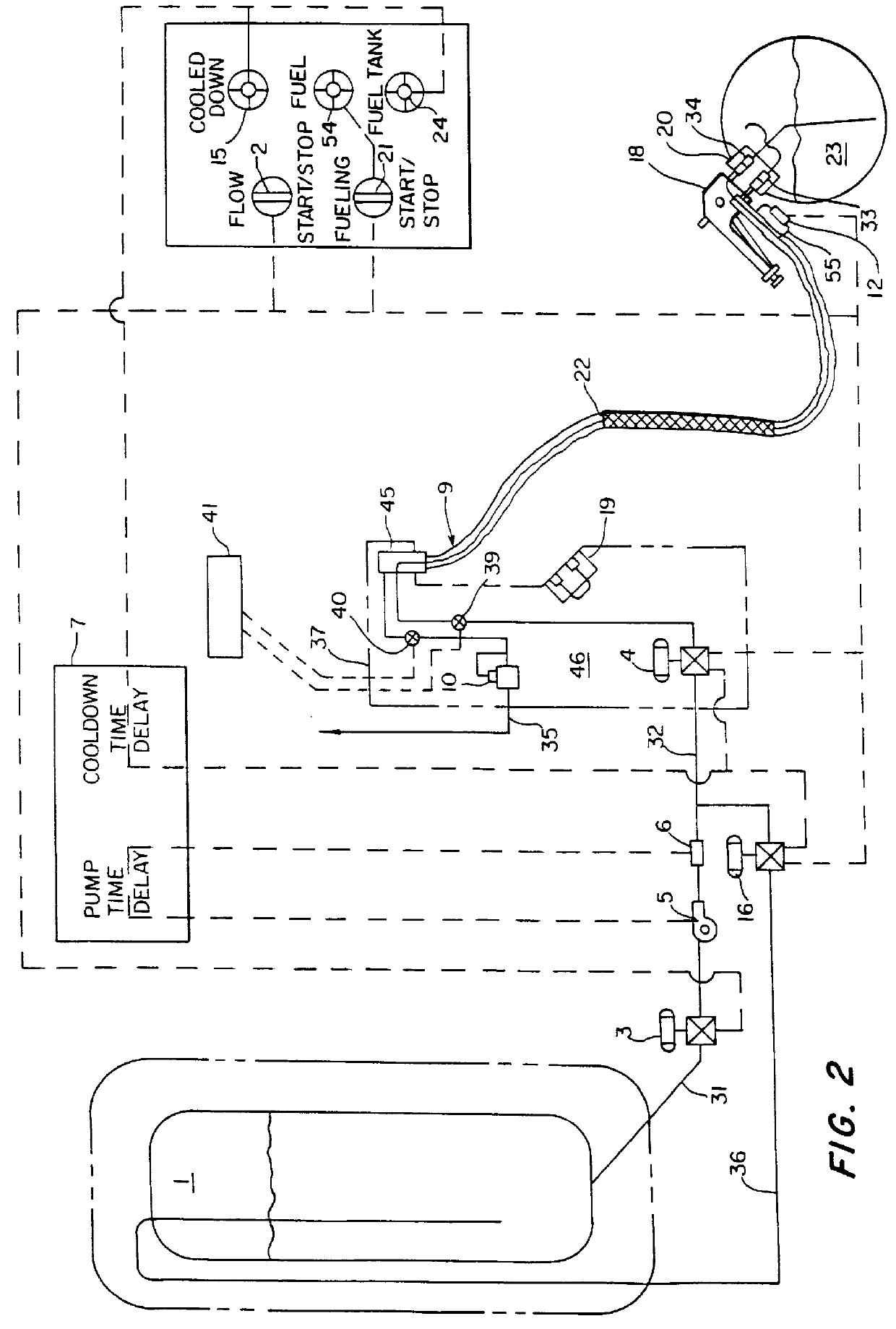
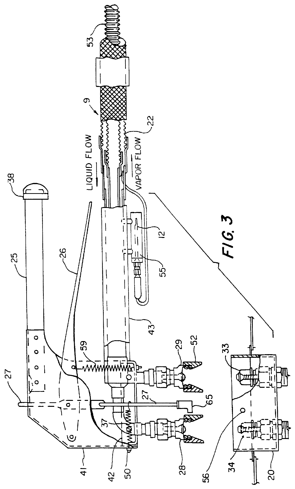
As shown in FIG. 1, a conduit 31 provides a flow path for the liquid contents of LNG tank 1 flow to the intake of a motor-driven pump 5. A conduit 32 provides a flow path from the pump discharge to a flexible delivery conduit 9. Within the delivery conduit are an inner passage, serving as an extension of conduit 32 and an annular outer passage 22 for return flow of vapor to a vapor recovery system by way of conduit 35 provided with pressure regulator 10. A delivery nozzle 18 is coupled to the free end of the flexible conduit and is provided with valved quick-disconnect fittings separately coupled to the inner and outer passages of the flexible conduit.

Motor-operated valves 3 and 4 are provided in conduits 31 and 32, respectively. A third motor-operated valve 16 is provided in recirculation conduit 36 extending from conduit 32, at a location between the pump discharge and valve 4, to the LNG tank. Conduit 32 is provided with a liquid sensor 6 at a location just downstream of the pump...


PUM

PropertyMeasurementUnit
Timeaaaaaaaaaa
Pressureaaaaaaaaaa

Abstract

An apparatus and method for efficiently metering and transferring a cryogenic liquid, such as liquefied natural gas, from a storage vessel to, for example, a vehicle fuel tank. The apparatus incorporates a programmable controller, a motor-driven pump and a network of conduits with motor-operated valves and liquid sensors for effecting a priming of the pump with liquid free of vapor and a cool-down of the flow passages prior to a transfer operation for ensuring that a vapor-free liquid is delivered. A pair of flow meters, one for liquid and the other for returned vapor, allows a reliable determination of the amount of liquid delivered to-and remaining in-a receiving vessel. The apparatus employs a delivery nozzle with quick-disconnect valved fittings and a delivery nozzle incorporating features which allow it to be handled by an operator without the use of heavy gloves. The method of transferring a cryogenic liquid employs an operating sequence with programmed time delays for ensuring that the liquid pump is properly primed and that the transfer apparatus is cooled down before liquid transfer begins.

Description

1. Field of the InventionThe present invention relates to an apparatus and a method for metering and transferring an extremely cold liquid from a supply vessel to a receiving vessel. The liquids intended for transfer by the apparatus and method of this invention exist as a gas at normal atmospheric temperature and pressure and will hereafter in this specification be identified as cryogenic liquids. The present invention is particularly adapted for, but not limited to, the efficient transfer of cryogenic liquid fuels, especially liquefied natural gas (LNG), or methane, from a storage tank to a vehicle fuel tank.2. Description of Prior ArtKnown apparatuses and methods for effecting the transfer of cryogenic liquids require a series of manual operations which require skilled operators, entail substantial time and expense and invite damage to equipment and loss of valuable cryogenic liquids. Also, due to the extremely cold temperatures of the liquids being handled, discomfort or injury ...

Claims


Application Information

Patent Timeline
IPC IPC(8): F17C5/00F17C6/00F17C13/02F17C13/00F17C7/02
CPCF17C5/007F17C7/02F17C13/02F17C13/021F17C13/023F17C6/00F17C2260/024F17C2205/0376F17C2265/065F17C2270/0139F17C2205/0364F17C2205/037F17C2221/033F17C2223/0161F17C2223/033F17C2227/0135F17C2250/0408F17C2250/0443F17C2250/0636
Inventor SUTTON, HAROLD E.ADKINS, ROY E.
Owner CRYOGENIC FUELS
Why Eureka
Try Eureka