Variable attenuator for satellite signals

a satellite signal and variable attenuator technology, applied in waveguide devices, instruments, antenna couplings, etc., can solve the problems of difficult for an installer to determine the peaking of signals, cumbersome and slow use, and inability to be automated

Inactive Publication Date: 2000-11-07
HUGHES ELECTRONICS
View PDF3 Cites 5 Cited by
  • Summary
  • Abstract
  • Description
  • Claims
  • Application Information

AI Technical Summary

Problems solved by technology

First, it is cumbersome and slow in use, and not susceptible to being automated.
With the method of the '596 patent, it would be difficult for an installer to determine signal peaking by observing the number or strength of the sparklies on the screen.
It is not readily adaptable for use with digital transmissions (such as digital DBS transmissions), as images displayed of digitally transmitted signals do not degrade gradually or produce visible noise-like phenomena on a television screen which could be monitored to determine an acceptable minimum signal strength.
Repeated use may therefore lead to damage and deterioration of the pads, reducing accuracy, convenience, and reliability.
The adjustments in attenuation produced by the stacked pads are limited in resolution to a few discrete values, and continuous changes in the amount of attenuation of the incoming satellite signal are not possible.
The '596 method thus suffers from lack of precision in determining the optimum satellite collector position.

Method used


Image

  • Variable attenuator for satellite signals
  • Variable attenuator for satellite signals
  • Variable attenuator for satellite signals

Examples


Embodiment Construction

)

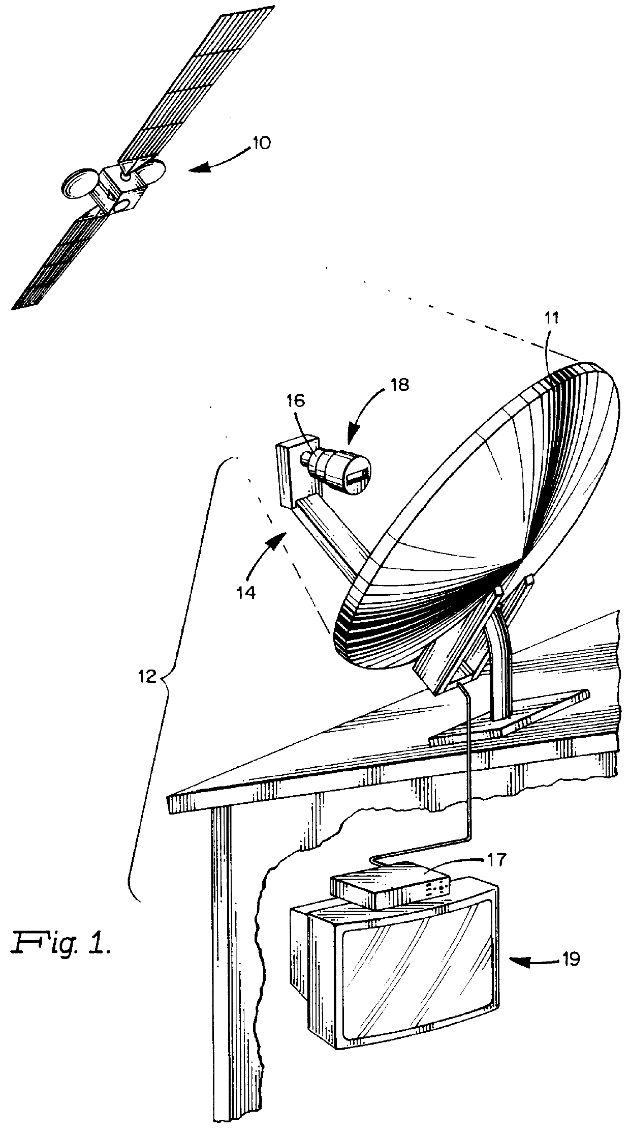
The satellite communication system illustrated in FIG. 1 comprises a satellite 10 transmitting RF signals to a satellite receiving system 12 comprising a collector 11, a receiving horn 14 including a low noise block converter or "LNB" 16 wherein the received satellite signals are amplified and converted as a block to intermediate frequencies. The output of the LNB 16 is supplied to an integrated receiver-decoder or "IRD" 17 wherein the signals are further processed and supplied, for example, to a television receiver 19, or to a recorder, audio receiver, computer, or other device.

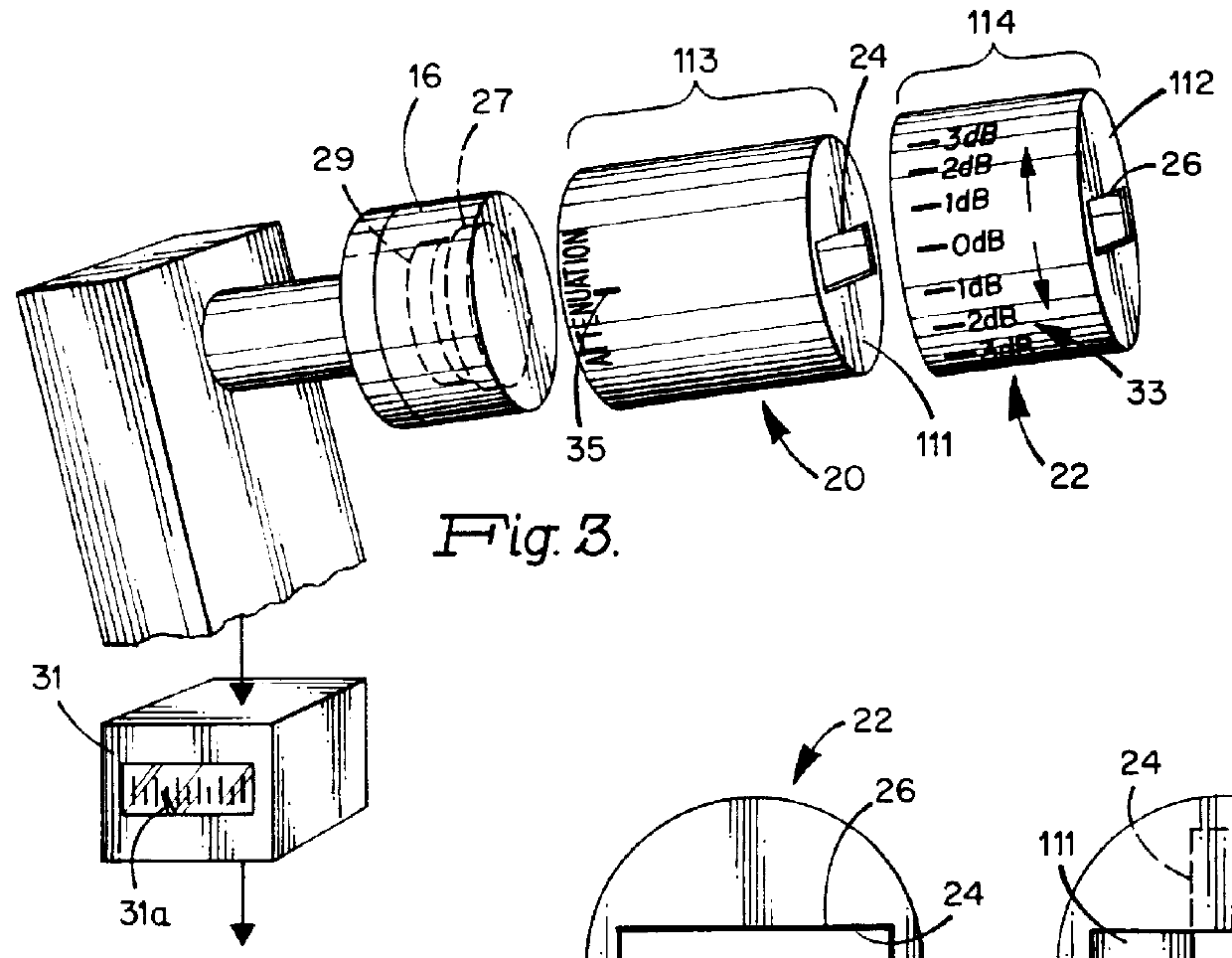
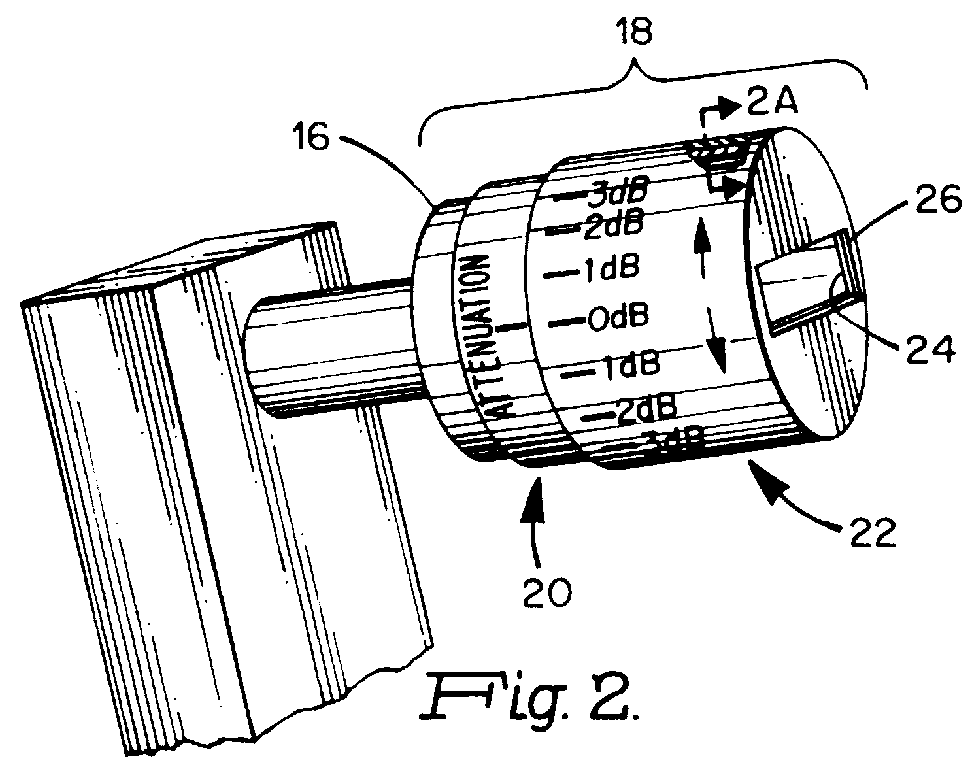
A variable signal attenuator 18 according to the present invention for selectively varying RF signals received from the satellite 10 is adapted to be mounted on the LNB 16. The mounting may be permanent or, in other embodiments, temporary (i.e. removable).

FIGS. 2-5 illustrate details of the variable signal attenuator 18. The signal attenuator 18 comprises a radiation shield having at least one selectively v...


PUM


Abstract

For use in or with a satellite receiving system having a receiving element such as low noise amplifier, a selectively variable RF signal attenuator locatable between the satellite and the amplifier comprises an RF radiation shield having at least one selectively variable radiation-passing area. The radiation shield comprises a plurality of overlapped shield members having selectively overlapped openings, movement of one member relative to the other causing the effective intersection defining a radiation-passing area of the shield to vary. According to a disclosed method, after locating a radiation attenuator as described between the satellite and the amplifier, the signal received from the satellite is variably attenuated using the signal attenuator until the signal level of the received radiation is within a range of an associated signal indicator wherein the indicator's response is more linear than it is at higher signal levels. The position of the collector is then adjusted until the indicator output peaks. Finally, the attenuation is reduced or eliminated to permit normal operation of the satellite receiving system.

Description

1. Field of the InventionThe invention relates to direct broadcast satellite systems, and particularly to improvements in aperture and method for collector alignment.With the advent of consumer satellite receivers, particularly satellite receivers having inexpensive small aperture collectors intended for optional installation by the user, it is of paramount commercial importance that the collector (and associated elements) be capable of being quickly, easily, and inexpensively aligned with a satellite whose transmission is to be received.Because of the small aperture of such collectors, they are necessarily designed to have high gain, making precise alignment especially critical. For example, 18-inch diameter offset-fed parabolic reflectors are used in present commercial systems, having a 3 dB beam width of only approximately 2 degrees. Low cost precise alignment of such collectors in a consumer environment has been challenging. Accurate aiming of such satellite collectors is of sig...

Claims


Application Information

Patent Timeline
Patent Type & Authority Patents(United States)
IPC IPC(8): H01Q19/13H01Q1/52H01P1/22H01Q1/00H01Q19/10
CPCH01P1/222H01Q19/132H01Q1/526
Inventor KUETHER, DAVID J.
Owner HUGHES ELECTRONICS
Why Eureka
Try Eureka