Flat plate heat pipe cooling system for electronic equipment enclosure

a technology for electronic equipment and enclosures, applied in the direction of insulated conductors, semiconductor/solid-state device details, instruments, etc., can solve the problems of obstructing the cooling air flow pathway, difficult to find clearance for tubular heat pipes within tightly packed enclosures, and large heat sinks extending out of the enclosure are vulnerable to damag

Inactive Publication Date: 2000-11-21
SCIENTECH
View PDF20 Cites 177 Cited by
  • Summary
  • Abstract
  • Description
  • Claims
  • Application Information

AI Technical Summary

Benefits of technology

to provide a means for removing heat from a tightly packed electronic equipment enclosure that does not rely on large amounts

Problems solved by technology

However when a large number of electronic components are densely packed into a small enclosure, as for example the chassis of a notebook or laptop computer, it is difficult to provide enough space between the components for heat sinks without obstructing pathways for cooling air flow.
While this system does not require heat sinks or cooling air flow within the enclosure, it may be difficult to find clearance for a large, tubular heat pipe within a tightly pack

Method used


Image

  • Flat plate heat pipe cooling system for electronic equipment enclosure
  • Flat plate heat pipe cooling system for electronic equipment enclosure
  • Flat plate heat pipe cooling system for electronic equipment enclosure

Examples


Embodiment Construction

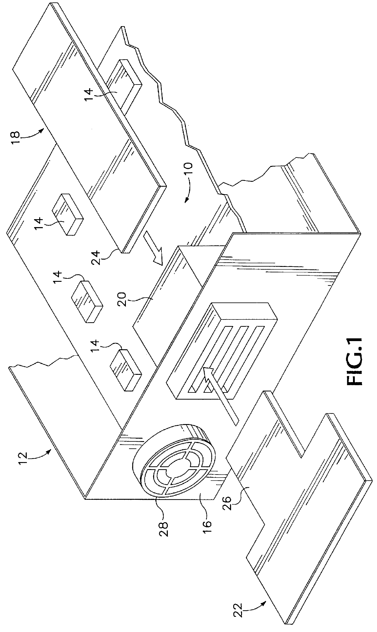
FIG. 1 illustrates in exploded cut-away perspective view a cooling apparatus 10 for removing heat from an enclosure 12 containing heat-generating electronic components 14. Cooling apparatus 10 includes a thin flat-plate heat pipe 18, a connector 20 mounted in, and extending through, a wall 16 of enclosure 12 and a removable card-like heat sink 22. Heat pipe 18 resides within enclosure 12 with one end 24 inserted into connector 20. Heat sink 22 resides outside of enclosure 12 and also has an end 26 inserted into connector 20. Ends 24 and 26 of heat pipe 18 and heat sink 22 thermally contact each other within connector 20.

Heat pipe 18 absorbs heat from the ambient air within enclosure 12 and directly from any component 14 that it may contact. The absorbed heat travels though heat pipe 18 to its end 24 within connector 20 where it passes into end 26 of heat sink 22. As the heat travels outward through heat sink 22 from end 26, heat sink 22 radiates that heat through its surfaces into t...


PUM


Abstract

A cooling system for an electronic equipment enclosure employs a flat plate heat pipe to deliver heat from the interior of the enclosure through a connector to a removable external heat sink. The heat pipe includes a metallic bottom plate having a depression therein containing a set of rods evenly spaced from one another. A top plate covers the bottom plate with the rods compressed therebetween. Channels formed between adjacent rods are partially evacuated and injected with an evaporative fluid. The fluid and its vapor circulate in the channels to convey heat from a warm end of the heat pipe to a cool end. The heat sink is of similar construction.

Description

1. Field of the InventionThe present invention relates in general to systems for cooling electronic components mounted in an enclosure and in particular to a cooling system employing a heat pipe to conduct heat to a heat sink outside the enclosure.2. Description of Related ArtWhen electronic components are installed in an enclosure, it is often necessary to remove the heat those components generate from the enclosure so that the components remain sufficiently cool to operate properly. The most common way to remove heat from an electronic component is through a metallic heat sink attached to the component. Heat travels by conduction from the component to the heat sink's fins which then radiate the heat into the surrounding air within the enclosure. A fan installed on an enclosure wall forces hot air away from the heat sink fins and out of the enclosure. However when a large number of electronic components are densely packed into a small enclosure, as for example the chassis of a note...

Claims


Application Information

Patent Timeline
IPC IPC(8): G06F1/20F28D15/02F28D15/04H01L23/34H01L23/427H05K7/20
CPCF28D15/0233F28D15/046G06F1/203H01L23/427H01L2924/0002H01L2924/00F28D15/0275
Inventor LI, HSI-SHANGHSIAO, CHEN-ANG
Owner SCIENTECH
Why Eureka
Try Eureka