Support base for a measuring cell

a technology for supporting bases and measuring cells, applied in the direction of measuring devices, instruments, weighing apparatus, etc., can solve the problems of increasing the overall height of the support base and the scale, unable to overcome the disadvantage of selecting an extremely hard material, and unable to transmit small forces

Inactive Publication Date: 2000-11-21
BORNGASSER JOHANNES
View PDF12 Cites 49 Cited by
  • Summary
  • Abstract
  • Description
  • Claims
  • Application Information

AI Technical Summary

Problems solved by technology

The joint described in the European Patent, however, is only able to transmit small forces because the ball contacts the planar surfaces the pressure head and the base plate, respectively, only at a single point and can therefore cause an indentation in the material.
Even the selection of an extremely hard material cannot overcome this disadvantage.
This approach, however, also increases the overall height of the support base and the scale which is a further disadvantage.
Another disadvantage is that since the connection between the pressure head and the rubber or plastic body does not provide any play, a displacement of the load pin distorts the rubber or plastic which, in turn, may affect the measurement process and misstate the results.
However the large diameter of the ball requires a relatively large support base.
Furthermore, if the load and the weighing platform move horizontally, then the ball may disadvantageously roll off and cause the pressure plates to come apart due to the concave shape of their surface area, thereby producing distortion and measurement errors.
This joint also produces measurement errors if the individual force transmitting elements became vertically misaligned.
This relative sliding motion of the components which is required for relative movement and displacement, requires adequate play between the two components that may noticeably distort the measurement results.
The sliding friction also causes excessive wear of the components.
Moreover, only small forces can be transmitted since the load is carried only by the screw connection located on both sides of the load pin.
The reduced complexity also the manufacturing costs of the base.

Method used


Image

  • Support base for a measuring cell

Examples


Embodiment Construction

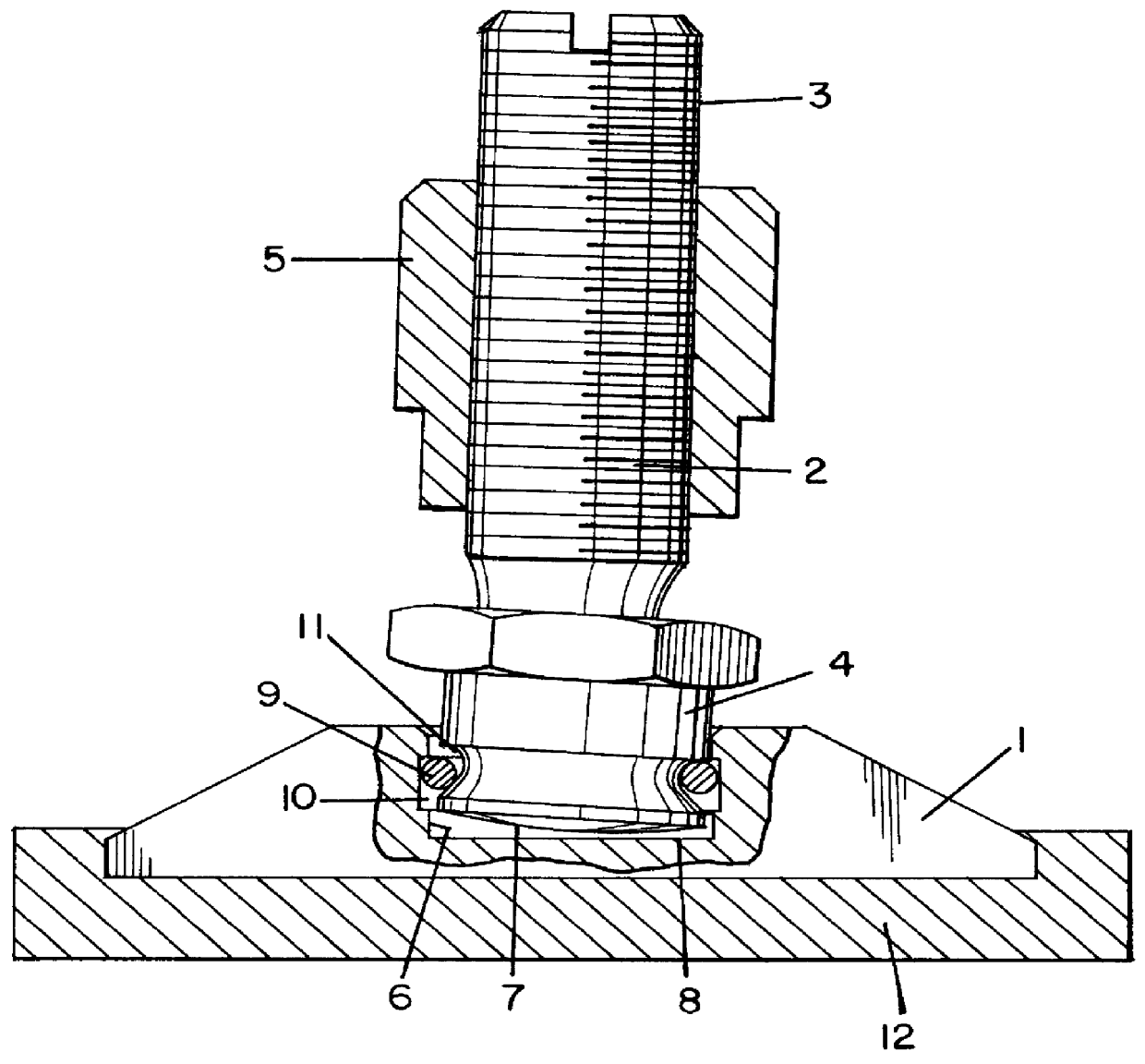
The support base in accordance with the present invention includes a base plate 1 and a load pin 2 that is under pressure. The load pin 2 has a threaded shank 3 that can be screwed in the measuring cell, and a pressure head 4 that is inserted in the base plate 1.

The threaded shank 3 is adapted to mate with a through hole or a blind hole located on the measuring cell. The shank's dimensions provide a variable insertion depth to allow sufficient height adjustment. A lock nut 5 provides a tight connection without clearance. If the measuring cell has a blind hole, then the thread length is rather short and the lock nut 5 is selected to be quite thick to occupy the space between the base plate 1 and the measuring cell and to provide additional support. If the measuring cell has a through hole, then a thinner lock nut 5 is employed.

The support joint is formed by the pressure head 4 in conjunction with a bore 6 located in the base plate 1. The front face of the pressure head 4 has a convex...


PUM


Abstract

PCT No. PCT/DE97/01266 Sec. 371 Date Jan. 29, 1999 Sec. 102(e) Date Jan. 29, 1999 PCT Filed Jun. 20, 1997 PCT Pub. No. WO98/00688 PCT Pub. Date Jan. 8, 1998A support base for a measuring cell including a base plate with a bore and an annular groove defined therein, and a planar pressure surface machined therein. A load pin is connected to the base plate to provide articulated support for a load. The load pin has a threaded shank adaptable to adjust its height relative to the measuring cell and terminates in a pressure head with a convex pressure surface and an annular groove defined therein. The pressure head of the load pin is inserted with play into the bore of said base plate. A resilient ring is disposed between the annular grooves to connect the base plate and the pressure head.

Description

1. Field of the InventionThe present invention relates to a support base for a measuring cell.2. Description of Related ArtSupport bases of this type and associated measuring cells are used primarily with scales, but for the installation of machines.A scale can be constructed as a platform scale or a tank scale and can include a weighing platform with at least three support bases and an equal number of measuring cells that respond to a pressure and to a twisting or shear load. Each support base is associated with a measuring cell.The support bases and the measuring cells are arranged at a certain distance from each other inside the platform area of the scale. The measuring cells represent elements that connect the weighing platform with the support bases. In other words, the housing of the measuring cells is secured to the weighing platform, whereas the measuring arm is attached to the support base.These scales are typically preassembled in the factory and are then adjusted at the i...

Claims


Application Information

Patent Timeline
Patent Type & Authority Patents(United States)
IPC IPC(8): G01G21/23G01G21/00
CPCG01G21/23Y10S177/09
Inventor BORNGASSER, JOHANNES
Owner BORNGASSER JOHANNES
Why Eureka
Try Eureka