Direct electrostatic printing apparatus having a magnetic brush with a core rotating at high speed
a technology of electrostatic printing and magnetic brushes, which is applied in the direction of electrographic process apparatus, printing, instruments, etc., can solve the problems of inaccurate and expensive means, change in image density, and inability to accurately and accurately print, etc., to achieve improved direct electrostatic printing, high density resolution, and high quality
Inactive Publication Date: 2000-11-21
AGFA GEVAERT AG
View PDF9 Cites 1 Cited by
- Summary
- Abstract
- Description
- Claims
- Application Information
AI Technical Summary
Benefits of technology
It is an object of the invention to provide an improved Direct Electrostatic Printing (DEP) device, printing high quality images with a high density resolution and with a high spatial resolution.
It is a further object of the invention to provide a DEP device combining high image quality with good long term stability and reliability.
It is another object of the invention to provide a DEP device printing images without density fluctuations at a high printing speed and wherein the clogging of printing apertures by agglomerated and / or deformed toner particles is avoided.
Problems solved by technology
The printing device as described in the original Pressman patent is very sensitive to changes in distances from the toner application module towards said shield electrode, leading to changes in image density.
Another deficiency is visible in the printing direction if the toner application module is a rotating roller that does not have the shape of a perfect balanced cylinder.
This, however, causes very accurate and expensive means to be used in order to fabricate a toner application module according to said invention.
Moreover, sliding contact, is never beneficial for excellent long term stability and reliability.
The main drawback of this system, however, is the consumption of toner particles from one side of a row of printing apertures to the other side, making it not possible to print with an equal density profile over the complete width of the receiver material.
The main drawback of this device is again the frictional contact over toner particles that greatly reduces the overall printing quality and long term stability.
Thus the printing apertures can be clogged by agglomerated or deformed toner particles, leading to images with missing dots and bad image quality.
Said low frequency, however, is obtained by using a very low rotational speed and in this case the amount of marking particles that can be provided towards said printhead structure is too low to get a high image density.
Method used
View moreImage
Smart ImageViewing Examples

Examples
example 1 (
E1)
Printing proceeded with a DEP device and a developer described above. The core of the magnetic brush rotated at 1500 rpm counter-clock wise and the sleeve at 3 rpm clock wise.
examples 2-5 (
E2-E5)
A printing configuration as described in example 1 was used, except for the fact that the rotation speed of the sleeve of said magnetic brush and of said magnetic core was changed as indicated in table 1.
Login to View More PUM
 Abstract
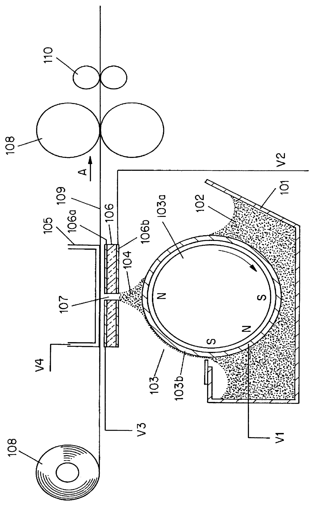
A DEP device is provided that comprises a printhead structure with control electrodes in combination with printing apertures and a magnetic brush assembly delivering a cloud of toner particles in the vicinity of the printing apertures, wherein the toner particles are, together with magnetically attractable carrier particles part of a multi-component developer further and the magnetic brush comprises a magnetic core rotating at a speed equal to or higher than 500 rpm (rotations per minute) and a sleeve rotating at a speed equal to or lower than 10 rpm (rotations per minute).
Description
DESCRIPTION1. Field of the InventionThis invention relates to an apparatus for use in the process of electrostatic printing and more particularly in Direct Electrostatic Printing (DEP). In DEP, electrostatic printing is performed directly from a toner delivery means on a receiving member substrate by means of an electronically addressable printhead structure.2. Background of the InventionIn DEP (Direct Electrostatic Printing) the toner or developing material is deposited directly in an imagewise way on a receiving substrate, the latter not bearing any imagewise latent electrostatic image. In the case that the substrate is an intermediate endless flexible belt (e.g. aluminium, polyimide etc.), the imagewise deposited toner must be transferred onto another final substrate. If, however, the toner is deposited directly on the final receiving substrate, a possibility is fulfilled to create directly the image on the final receiving substrate, e.g. plain paper, transparency, etc. This depo...
Claims
Login to View More Application Information
Patent Timeline
 Patent Type & Authority Patents(United States)
IPC IPC(8): G03G15/00G03G15/34
CPCG03G15/346G03G2217/0025
Inventor DESIE, GUIDOBRODDIN, DIRK
Owner AGFA GEVAERT AG
Features
- R&D
- Intellectual Property
- Life Sciences
- Materials
- Tech Scout
- Unparalleled Data Quality
- Higher Quality Content
- 60% Fewer Hallucinations
Learn More Browse by: Latest US Patents, China's latest patents, Technical Efficacy Thesaurus, Application Domain, Technology Topic, Popular Technical Reports.
© 2025 PatSnap. All rights reserved.Legal|Privacy policy|Modern Slavery Act Transparency Statement|Sitemap|About US| Contact US: help@patsnap.com