Self-diagnostic blood pressure measuring apparatus

a self-diagnostic and measuring device technology, applied in the field of self-diagnostic blood pressure measuring apparatus, can solve the problems of insufficient prior apparatus to give direct and exact blood pressure information to the user, display is difficult to indicate direct relation between the individual blood pressure being measured and the associated zone, and display is difficult to give a warning by reference to the zon

Inactive Publication Date: 2000-11-28
MATSUSHITA ELECTRIC WORKS LTD
View PDF9 Cites 40 Cited by
  • Summary
  • Abstract
  • Description
  • Claims
  • Application Information

AI Technical Summary

Problems solved by technology

However, this display is difficult to indicate direct relation between the individual blood pressures being measured and the associated zone.
Particularly, when only one of the systolic and diastolic pressures

Method used


Image

  • Self-diagnostic blood pressure measuring apparatus
  • Self-diagnostic blood pressure measuring apparatus
  • Self-diagnostic blood pressure measuring apparatus

Examples


first embodiment

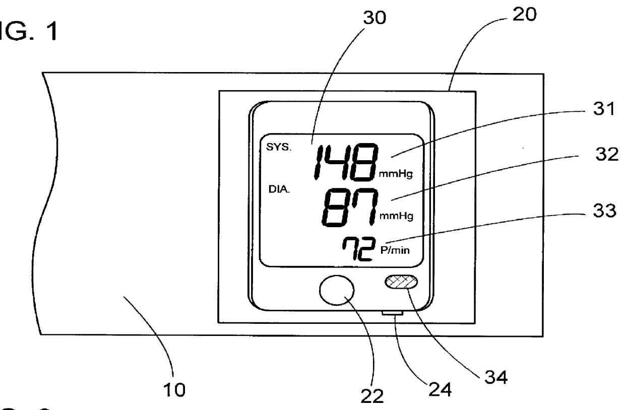
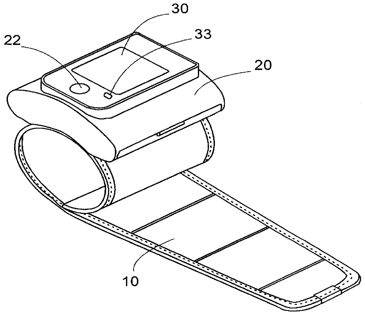
FIG. 2 illustrates a self-diagnostic blood pressure measuring apparatus in accordance with a preferred embodiment of the present invention. The apparatus includes an occluding cuff 10 adapted to be wound around a human's wrist, a housing 20 secured to a portion of the cuff 10. The housing 20 has a start switch 22 for starting a blood pressure measurement and a display unit for the measured results. The display unit is composed of a liquid-crystal display (LCD) 30 and a light emitting diode (LED) lamp 34. The housing 20 incorporates a pneumatic pump for inflating or collapsing the cuff 10 and an electronic circuitry for the blood pressure measurement. Mounted within the cuff 10 are a microphone for picking up the Korotocoff sound and a pressure sensor for detecting an occluding pressure. Based upon the information of the Korotocoff sound and the pressure, a blood pressure measuring circuit 50 within the housing 20 operates to measure systolic and diastolic pressures. Further, a heat ...

first modification

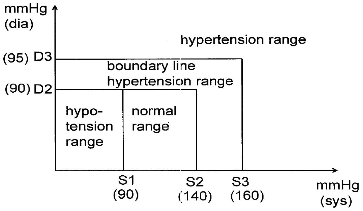
In order to simplify the configuration of the blood pressure measuring apparatus, the LED lamp 34 may be eliminated so that the first and second numerical indicators 31 and 32 are caused to be highlighted by blinking when the systolic and diastolic pressures exceed S2 (=140 mmHg) and D2 (=90 mmHg), respectively for hypertension warning.

second modification

Although the above embodiment is contemplated to highlight the first and second numerical indicators 31 and 32, a modification may be made to highlight the indicators by changing the colors thereof, in addition to or instead of the blinking these indicators.


PUM


Abstract

A self-diagnostic blood pressure measuring apparatus displays a diagnostic result for each of the measured systolic and diastolic pressures for warning to an user. The apparatus includes has a detector which measures systolic and diastolic pressures thereof, a display unit having first and second numeric indicators respectively for displaying individual numerical values of the measured systolic and diastolic pressures. A diagnosing circuit is included to compare the measured systolic and diastolic pressures respectively with predetermined systolic and diastolic reference ranges so as to provide a systolic warning when the systolic pressure is out of the systolic reference range and provide a diastolic warning when the diastolic pressure is out of the diastolic reference range. The display unit includes a warning display section which notify the systolic and diastolic warnings, individually. Thus, the systolic and diastolic warnings can be individually displayed together with the measured systolic and diastolic pressures appearing at the first and second numeric indicators, thereby providing detailed blood pressure information for immediate recognition by the user.

Description

1. Field of the InventionThe present invention is directed to a self-diagnostic blood pressure measuring apparatus, more particularly to such apparatus which notifies an user of a blood pressure warning after displaying systolic and diastolic pressures.2. Description of the Prior ArtJapanese Patent Publication No. 60-132538 discloses a prior blood pressure measuring apparatus which has, in addition to displaying measured systolic and diastolic pressures, a self-diagnostic function of indicating a particular blood pressure stage in which a combination of the measured systolic and diastolic pressures is classified according to regulation by World Health Organization (WHO). Thus, the user can check one's blood pressure with the help of the diagnostic result which is shown by highlighting one of zones provided in a diagnostic display. That is, the display includes three separate zones defined by systolic values and diastolic values respectively given along x-axis and y-axis to have norm...

Claims


Application Information

Patent Timeline
IPC IPC(8): A61B5/022A61B5/024A61B5/0255
CPCA61B5/0255A61B5/02233
Inventor OKADA, KOICHI
Owner MATSUSHITA ELECTRIC WORKS LTD
Why Eureka
Try Eureka