Pulse wave detecting device and pulse measurer

a pulse wave and detecting device technology, applied in the field of pulse wave detecting devices, can solve the problems of inability to accurately calculate the pulse rate, the analog filter provided at the input stage does not sufficiently remove the effects of the analog filter, and other noise may be superimposed on the output of the pulse wave detecting sensor, so as to improve the processing accuracy and the accurate waveform of the pulse wave

Inactive Publication Date: 2000-12-05
SEIKO EPSON CORP +1
View PDF2 Cites 61 Cited by
  • Summary
  • Abstract
  • Description
  • Claims
  • Application Information

AI Technical Summary

Benefits of technology

As explained above, the present embodiment enables damping or removal of noise components in a pulse wave signal by employing first through third digital filters 506.about.508. As a result, it is possible to improve the accuracy of processing to detect the puls...

Problems solved by technology

However, in addition to the pulse wave components, other noise may be superimposed on the output from the pulse wave detecting sensor.
Since this superimposed noise is not necessarily regular, merely providing an analog filter at the input stage does not sufficiently remove its effects.
Thus, since frequency analysis is performed on the pulse wave signal containing the superimposed impulse noise as shown in the figure, it is not possible to accurately calculate the pulse rate.
Accordingly, if frequency analysis is carried out on a pulse wave signal containing a superimposed body motion component, the correct pulse rate cannot be calculated.
However, general impulse noise may also occur which...

Method used


Image

  • Pulse wave detecting device and pulse measurer
  • Pulse wave detecting device and pulse measurer
  • Pulse wave detecting device and pulse measurer

Examples


Embodiment Construction

Embodiments of the present invention will now be explained with reference to the accompanying figures. Note that the pulse measurer according to these embodiments is provided with the functions of a regular digital wristwatch, and is employed by switching between a watch mode and a pulse measurer mode.

A: STRUCTURE OF EMBODIMENT

A-1: Overall Structure

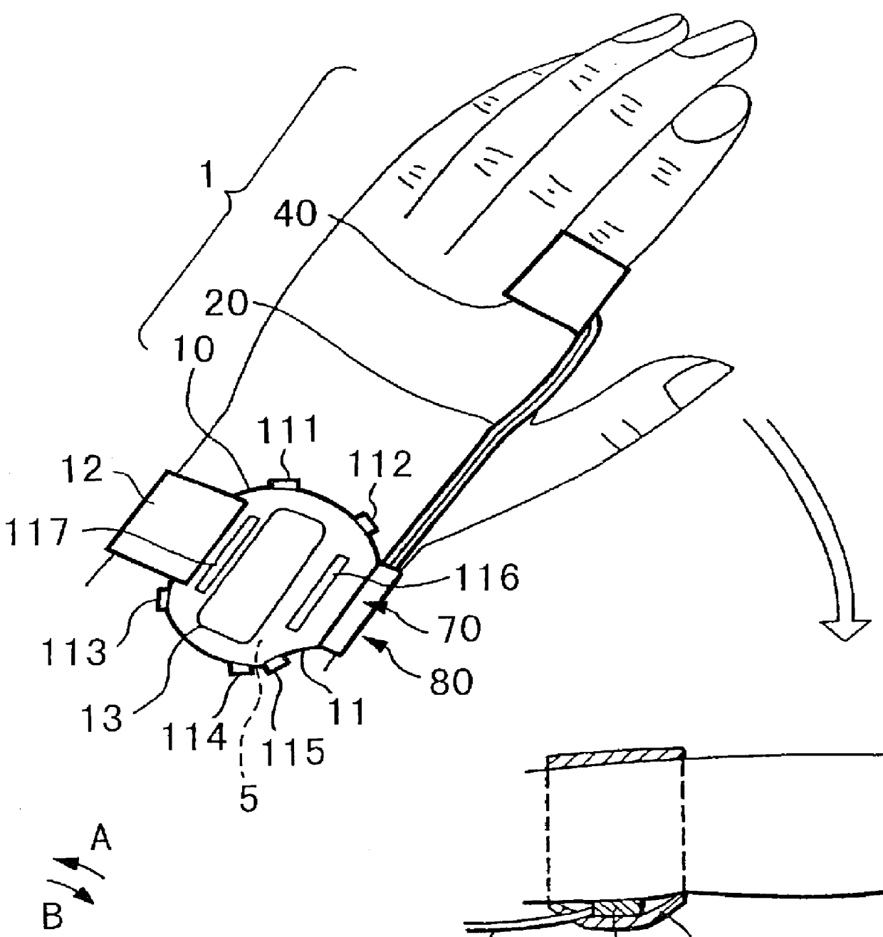
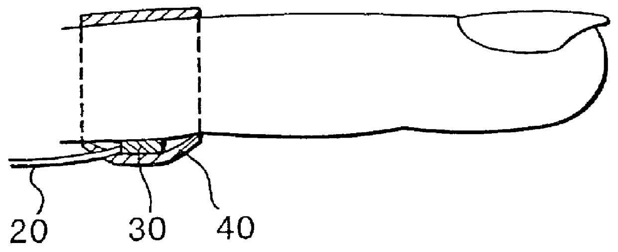
FIG. 1 shows the state of attachment of the pulse measurer, with the device roughly comprised of a device main body 10 having a wristwatch structure, a cable 20 connected to device main body 10, and a sensor unit 30 (pulse wave detecting sensor) provided to the end of cable 20. A wristband 12 is attached to device main body 10 which wraps around the user's wrist from the 12 o'clock position and affixes at the 6 o'clock position of the wristwatch. Device main body 10 can be freely attached and removed from the user's wrist by means of this wristband 12. Pulse wave detecting sensor unit 30 is blocked from light by band 40 employed for fixin...


PUM


Abstract

PCT No. PCT/JP98/01128 Sec. 371 Date Nov. 4, 1998 Sec. 102(e) Date Nov. 4, 1998 PCT Filed Mar. 17, 1998 PCT Pub. No. WO98/41143 PCT Pub. Date Sep. 24, 1998The present invention relates to a pulse wave detecting device for detecting pulse waves, and to a pulse measurer employing this pulse wave detecting device. The present invention addresses the problem of obtaining a pulse wave signal in which the noise components have been suitably removed from a pulse waveform, and of determining the pulse rate with high accuracy based on this pulse wave signal. The method for deriving the pulse wave signal and pulse rate is as follows. The pulse wave signal from pulse wave detecting sensor unit (30) is temporarily stored in buffer (503). When impulse noise is detected in the pulse wave signal in buffer (503) by impulse noise detecting means (505), the band pass for first digital filter (506) becomes a hill-shaped curve centered on the frequency corresponding to the preceding pulse rate, and impulse noise in the pulse wave signal output from buffer (503) is decreased. Thereafter, overall noise and body movement components are decreased in the pulse wave signal by means of second digital filter (507) and third digital filter (508). The signal is then subjected to frequency analysis by frequency analyzer (509), and the pulse rate is calculated from the results of this analysis.

Description

1. Field of the InventionThe present invention relates to a pulse wave detecting device for detecting pulse waves, and to a pulse measurer employing the aforementioned pulse wave detecting device.2. Description of the Related ArtPulse measurers which detect pulse waves, calculate the pulse rate, and then notify the user of the calculated result have been commercially available for some time. This type of pulse measurer calculates the pulse rate using the signals (pulse wave signals) output from a pulse wave detecting sensor that is disposed near a site on the user's body where the pulse measurement is to be made. Known methods for calculating the pulse rate include the rectangular wave processing method and frequency analysis method described below.(A) Rectangular wave processing methodIn the rectangular wave processing method, the pulse wave signal is converted to a rectangular wave, and the pulse rate is calculated by measuring the period of the rectangular wave (the pulse rate is...

Claims


Application Information

Patent Timeline
IPC IPC(8): A61B5/024A61B5/11A61B5/0245
CPCA61B5/024A61B5/721A61B5/02438A61B5/02427A61B5/7257A61B5/02455
Inventor KOSUDA, TSUKASANAKAMURA, CHIAKI
Owner SEIKO EPSON CORP
Why Eureka
Try Eureka