Solenoid valve for an electrically controlled valve

a technology of solenoid valve and valve body, which is applied in the direction of valve operating means/release devices, machines/engines, and fluid pressure injection control. it can solve the problems of armature reverberation after the valve body, valve armature oscillation,

Inactive Publication Date: 2000-12-19
ROBERT BOSCH GMBH
View PDF6 Cites 71 Cited by
  • Summary
  • Abstract
  • Description
  • Claims
  • Application Information

AI Technical Summary

Problems solved by technology

The disadvantage of the known solenoid valve is comprised in that when operating, an oscillation of the armature and / or rebounding of the valve member can occur, which is particularly disadvantageous if a rapid switching sequence of the solenoid valve is required and an injection should be executed that is divided into a pre-injection and a main injection, controlled by the solenoid valve.
However, here too, there is a disadvantage in that the armature reverberates after the valve member is placed on its seat.

Method used


Image

  • Solenoid valve for an electrically controlled valve
  • Solenoid valve for an electrically controlled valve
  • Solenoid valve for an electrically controlled valve

Examples


Embodiment Construction

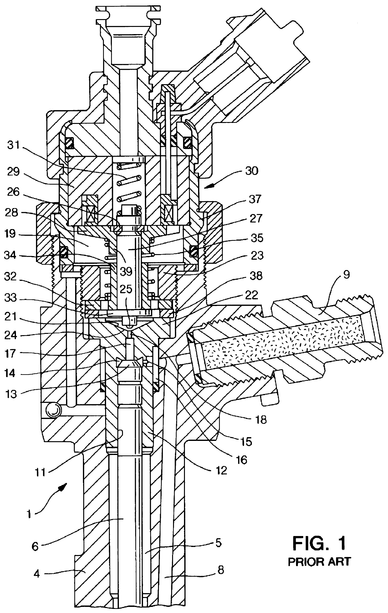
FIG. 1 shows a partial section through an electrically controlled injection valve 1 as is known, for example, from the prior art mentioned at the beginning. An injection valve of this kind is designated for use in a fuel injection system that is equipped with a high-pressure fuel reservoir, which is continuously supplied with high-pressure fuel by means of a high-pressure fuel pump and from which this fuel can be supplied at injection pressure to the internal combustion engine by way of individual, electrically controlled injection valves. The injection valve 1, which is shown partially and in a sectional view, additionally has an injection valve housing 4 with a longitudinal bore 5 in which a valve piston 6 is contained, which on its one end, acts on a valve needle, not shown in detail, which in turn cooperates with injection openings of the fuel injection valve in a known manner, e.g. which is shown in the reference EP 0 690 223 mentioned at the beginning. The valve piston 6 is us...


PUM


Abstract

PCT No. PCT/DE97/02723 Sec. 371 Date Oct. 28, 1998 Sec. 102(e) Date Oct. 28, 1998 PCT Filed Nov. 20, 1997 PCT Pub. No. WO98/38426 PCT Pub. Date Sep. 3, 1998A solenoid valve comprising a magnet armature which is embodied as having multiple parts and has an armature disk and an armature bolt. The magnet armature is guided in a slider. A damping device is provided in order to prevent post-pulse oscillation of the armature after a closing of the solenoid valve. The required short switching times of the solenoid valve can be exactly maintained with a device of this kind. The solenoid valve is designated for use in injection systems with a common rail.

Description

PRIOR ARTThe invention relates a solenoid valve for an electrically controlled valve. A solenoid valve of this kind has been disclosed by EP 0 690 223 A2. It is used there to control an electrically controlled fuel injection valve. The valve needle of the fuel injection valve is loaded in the closing direction by a pressure prevailing in a control chamber. The solenoid valve operates in a known manner so that to initiate the injection, it initiates a discharge of the control chamber when the magnet of the solenoid valve is excited and consequently, the valve needle of the injection valve is lifted up from its seat through the action of the high pressure acting on it from the other side. In the solenoid valve, the armature is connected to the armature bolt against which the valve member of the solenoid valve in turn rests.The disadvantage of the known solenoid valve is comprised in that when operating, an oscillation of the armature and / or rebounding of the valve member can occur, wh...

Claims


Application Information

Patent Timeline
Patent Type & Authority Patents(United States)
IPC IPC(8): F02M59/00F02M59/46F02M47/02F02M63/00F02M47/00F02M51/00F02M51/06F02M61/20
CPCF02M47/027F02M63/0017F02M63/0036F02M2547/003F02M2200/304F02M63/0022F02M63/022F02M47/02F02M59/46
Inventor BAUMGARTNER, PETERDRUMMER, EUGENRENNER, JOHANNES
Owner ROBERT BOSCH GMBH
Why Eureka
Try Eureka