

Method and apparatus for variably controlling the temperature in a selective deposition modeling environment
- Summary
- Abstract
- Description
- Claims
- Application Information
AI Technical Summary
Benefits of technology
Problems solved by technology
Method used
Image

Examples
first embodiment
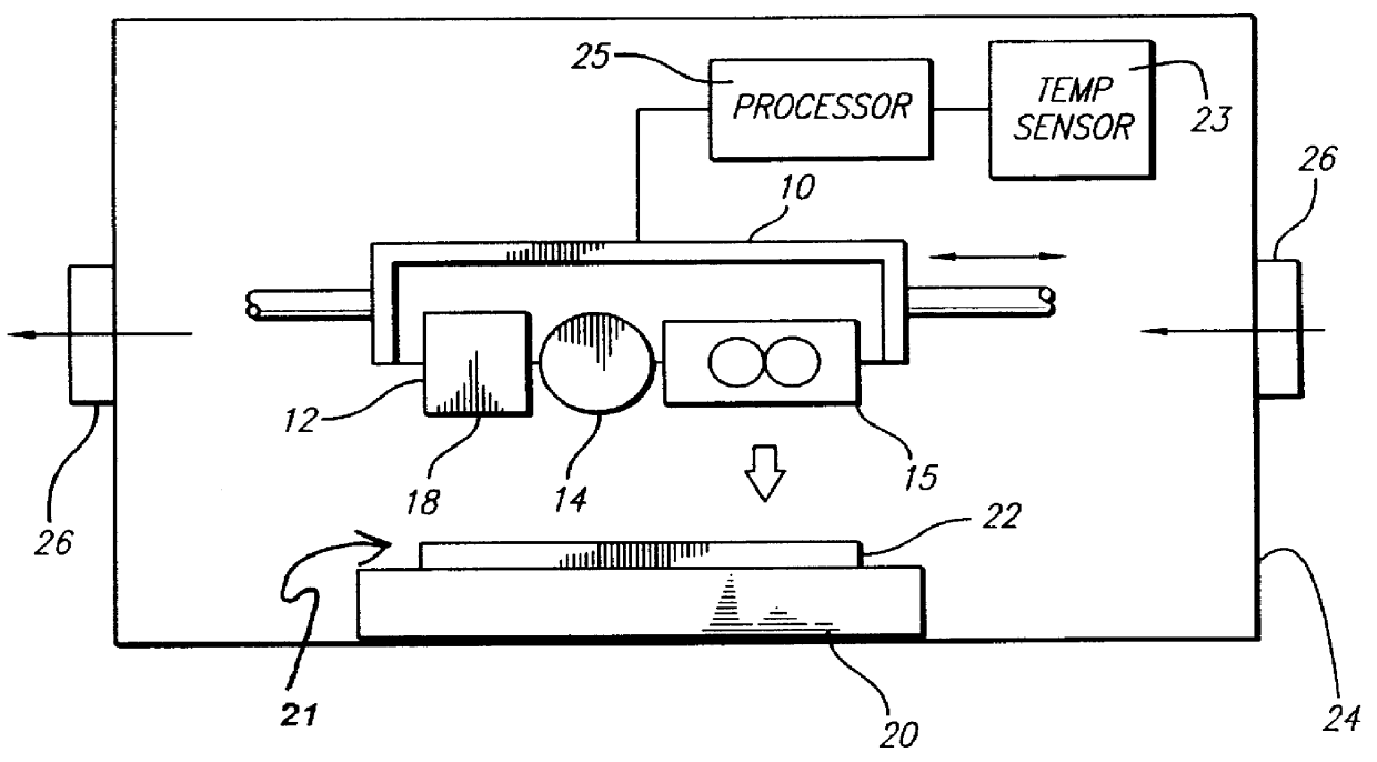
In the instant invention, the temperature of the three-dimensional object being formed is detected. A mechanism for detecting the temperature is preferably located in a chamber 24 that houses the apparatus for performing Selective Deposition Modeling (also referred to as the build environment). The temperature can be detected using, for example, an infra-red sensor or other well known temperature measuring devices. FIG. 1 includes a block diagram representation of a temperature sensor 23 coupled to a suitable processor 25 for controlling the fans 15 and 26 based on the sensed temperature and a suitable processor control program.
Based on the detected temperature of the three-dimensional object being formed, the number of fans and / or the flow rate produced by each fan is variably controlled For example, if the temperature of the three-dimensional object is too hot (e.g., above a preset threshold value defined by the processor program), one or more fans are operated under control of th...
second embodiment
In an alternative configuration of the second embodiment, the geometry of the object (and / or layer) being built or about to be built can be detected by software or by any other known device used to detect geometry. Another alternative involves using the geometry of previously dispensed material to define the quantity and temperature of gas applied to currently dispensed material. The geometry of any layer of the object can be determined from the software files (or run-time data) used in the Selective Deposition Modeling process to control the print head deposition to form the object or layer. In some cases, successive layers of material have a similar geometry. Therefore, the geometry of a previous layer can be used to estimate the geometry of a subsequent layer. Thus, the number of fans, the flow rate of the fans and / or the temperature of the gas blown by the fans and applied to the surface of a three-dimensional object can be based on the geometry of the layer to be dispensed or o...
fourth embodiment
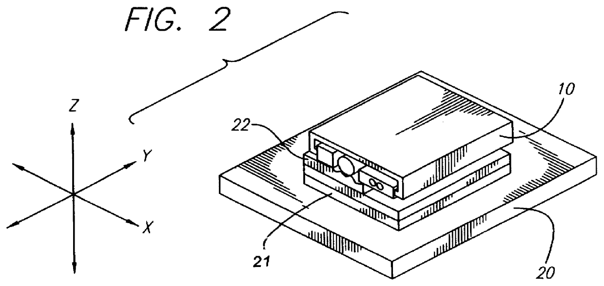
the instant invention involves forming a three-dimensional object in a build environment and detecting the temperature of the build environment. The build environment preferably comprises a closed chamber that houses the head carriage 10 and build platform 20 for performing Selective Deposition Modeling. A suitable mechanism for detecting the temperature can be located in the build environment.
The temperature can be detected using for example, but not limited to a thermistor, an infra-red sensor or other temperature measuring devices. Accordingly, the number of operating fans, the flow rates provided by the fans and / or the temperature of the gas blown by the fans and applied to the surface of the three-dimensional object is variably controlled based on the detected temperature in the build environment.
PUM
| Property | Measurement | Unit |
|---|---|---|
| Temperature | aaaaa | aaaaa |
| Time | aaaaa | aaaaa |
| Thickness | aaaaa | aaaaa |
Abstract
Description
Claims
Application Information