
Modular station platform construction kit

Inactive Publication Date: 2001-01-16
HERING
View PDF1 Cites 19 Cited by
  • Summary
  • Abstract
  • Description
  • Claims
  • Application Information

AI Technical Summary

Benefits of technology

Compared to the station platform according to the invention, the height-adjustable station platforms known from the prior art (DE 42 05 192 A1 and Verkehrstechnik 24, 666) do not have lateral displaceability, since the traffic island is guided by means of the shaft excavation and the platform system by means of securing elements. In contrast, with the platform according to the invention, it is also possible to react to changes in dimensions which occur, for example, at the transition from various customary platform heights (e.g. 38 cm above the SOK) to higher levels (e.g. 55-96 cm above the SOK). Particularly from the aspect of current demands for convenience and safety, such differences can no longer be tolerated without correction. Furthermore, the inventive production of the platform slab from various prefabricated components, instead of concrete cast in situ, has various advantages over DE 42 05 192 A1. For instance, with the prefabricated construction of the platform slab, the width of one platform slab is determined only by the maximum possible transport dimensions or weights. In contrast, in DE 42 05 192 A1, the width of the platform is limited by the permanent formwork. Moreover, a platform slab which has been prefabricated at the works can be used immediately after assembly. This considerably shortens the obstruction times on site since, as is well-known, concrete cast in situ must be allowed to set for up to 28 days. Additionally, prefabricated parts can also be assembled under extreme temperatures (frost). This is not the case with casting concrete in situ. This also results in greater flexibility with regard to the construction time.
This method according to the invention can be carried out with extremely little outlay and without great and prolonged interruptions of the rail operation. In particular, it is also possible to carry out small-scale corrections within the range of centimeters. Instead of replacing all the spacer elements, support elements between the components of the prefabricated kit can also be renewed or built up. This is because it is customary according to the prior art to attach so-called elastomer supports between such construction elements, e.g. in the form of neoprene strips. These support elements are arranged, on the one hand, between the platform slab and the spacer element and, on the other hand, the spacer element and the foundation. The toothed profile of the components reliably prevents horizontal displacement of the elastomer supports. Dimension tolerances in the platform slab and in the concrete foundation cast in situ or prefabricated foundation can also be compensated without difficulty by introducing non-shrinking grouting compound below the spacer elements or the platform slab.

Problems solved by technology

However, static structures of this kind no longer meet the requirements of modern rail traffic.
On the one hand, they are inflexible with regard to requirements emanating from new technical developments.
On the other hand, they do not provide the possibility of carrying out unavoidable corrections relating to dimensions and spacings on the structure at a later time in a straightforward and cost-effective manner.
Under the modern requirements for comfort and safety, it is no longer acceptable to tolerate such deviations without correction.
Moreover, the conventional station platforms are to be criticized from a current standpoint for the complex, time-consuming and cost-intensive construction which impedes operation.
A station platform system of this type may reduce the construction time of a station platform compared to the fixed construction, but the handling of the solid longitudinal beams and the many platform slabs is still relatively complex.
Moreover, the platform slabs are not protected against bending or "sagging" toward the unsupported center between the two longitudinal beams.
A particular disadvantage should furthermore be mentioned, that the station platform is not suitable for later reconstruction without difficulty due to the permanently applied connection of the construction elements and, in particular, does not permit any dimensional adaptation of the system at all.
This system has similar disadvantages to those described above.
In particular, no provision is made for dimensional adaptation and height-adjustability, and the fixed connection of the components to one another results in a structure which cannot easily be changed at a later date.
However, this production on site also has several disadvantages.
The width of the station platform is therefore limited for purely structural reasons because of the high loads exerted by the concrete covering cast in situ on the permanent formwork.
Additionally, influences of weathering and frost may impede the construction site.
This slab can only be removed by cutting the concrete.
The destruction of the reinforcement therefore makes its reusability extremely limited.
The height-adjustability of the traffic island or the platform system disclosed in the abovementioned publication and in DE 42 05 192 A1 can, however, result in problems in practice, since the desired spacing of the platform edge from the axis of the track may vary between customary platform heights (e.g. 38 cm above the upper edge of the rails (SOK)) and greater platform heights (e.g. 55 cm, 76 cm and 96 cm above the SOK).
In these cases, the height-adjustment may result in an undesirably and unacceptably large distance of the platform from the axis of the track or from the entrance to the carriage.
With this design, a platform is obtained, which avoids the disadvantages of the prior art that, after a change in height, the horizontal distances from the axis of the track are unfavorable or unacceptable from the viewpoint of convenience and safety.
Particularly from the aspect of current demands for convenience and safety, such differences can no longer be tolerated without correction.
In this case, the destruction of the reinforcement greatly restricts the reusability.
In the case of concrete cast in situ, this would mean an additional operation or even a greater maintenance outlay due to the poorer quality of the connection of the top covering to the platform slab.
In this case, however, the retention against unintentional lateral displacement must be such that it does not prevent lateral variability which is required for the reconstruction of the platform.
Generally, however, the surface pressure resulting from the weight of the system platform and its fitting elements is so small that the abovementioned foundation is sufficient.

Method used


Image

  • Modular station platform construction kit
  • Modular station platform construction kit
  • Modular station platform construction kit

Examples


Embodiment Construction

Of the area of the platform edge: a 30-50 cm wide strip with a structure providing particularly good grip (e.g. five-piece pattern, checkerplate pattern, other shapes),

Of the tactile guide strip: a 25 cm wide guide marking provided with a signal color, e.g. knob structure according to ADA and ACD,

Of the platform: plaster structure, various options possible.

The drainage-water is collected in an outlet channel and either fed to the soil in a drainage pit or conducted into the sewers. A transverse inclination of 1-2% of the system platform relative to the side remote from the track or (generally) relative to the center reliably ensures uniform drainage of the water. In the case of different heights of the two tracks leading along the central platform, an even gradient toward the central drainage point is ensured, in that the slab widths can be varied so that an even gradient is maintained from both sides.

In a further possible design, the water can be collected centrally at one or more ...


PUM


Abstract

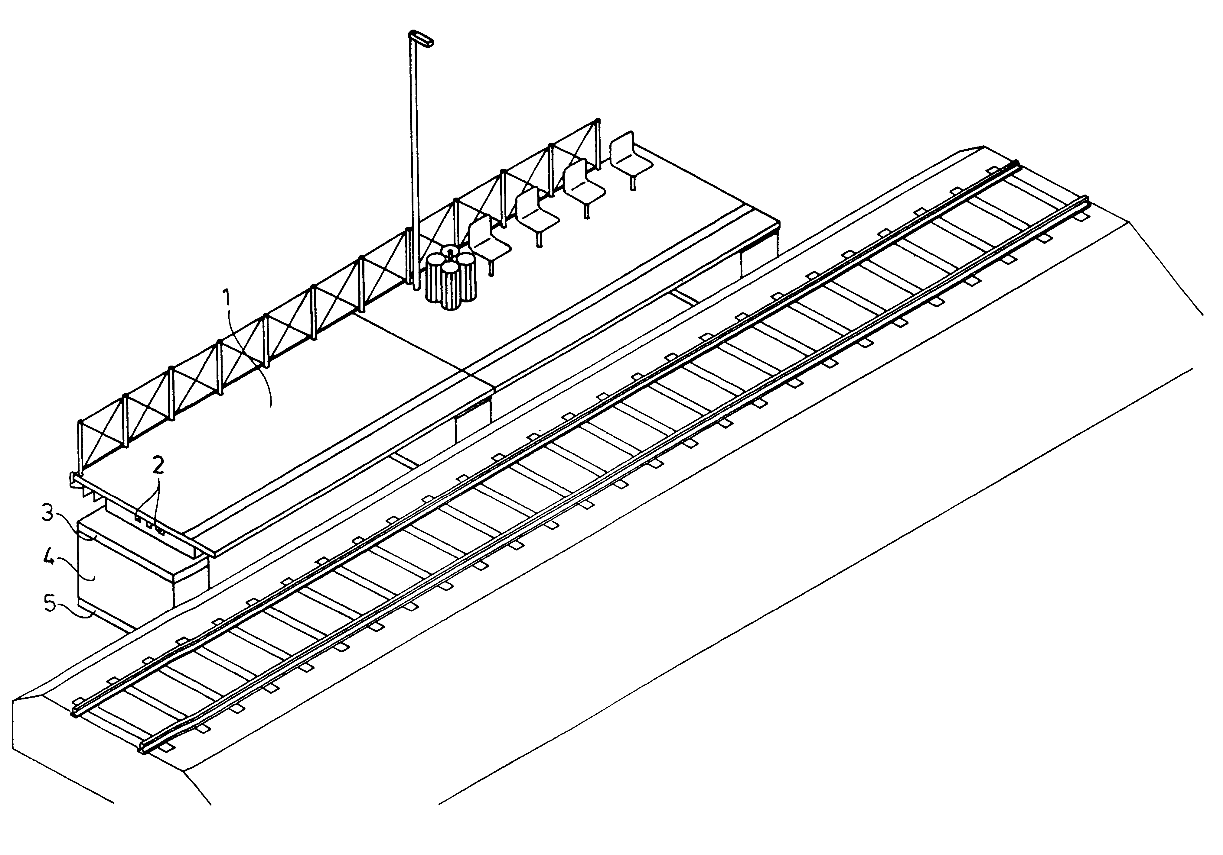
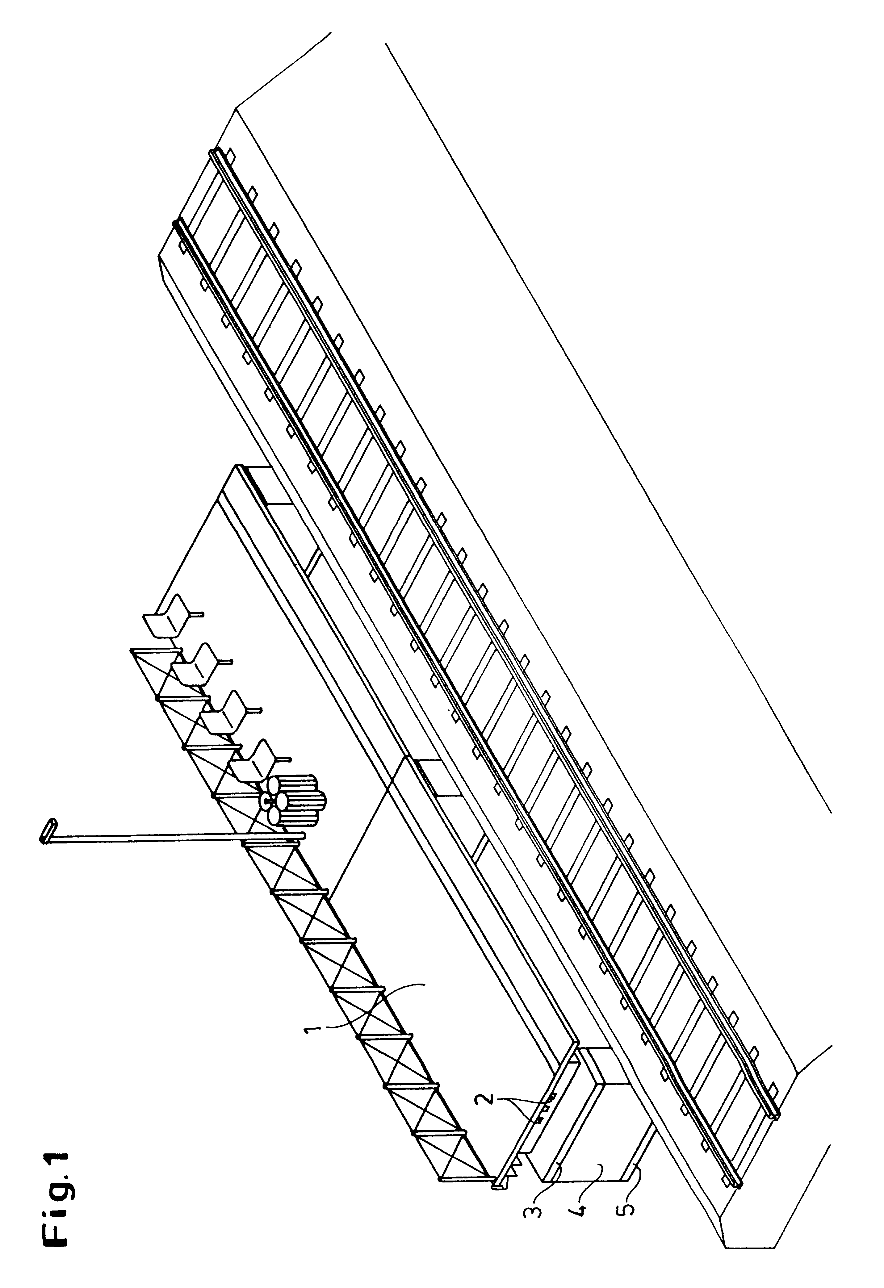
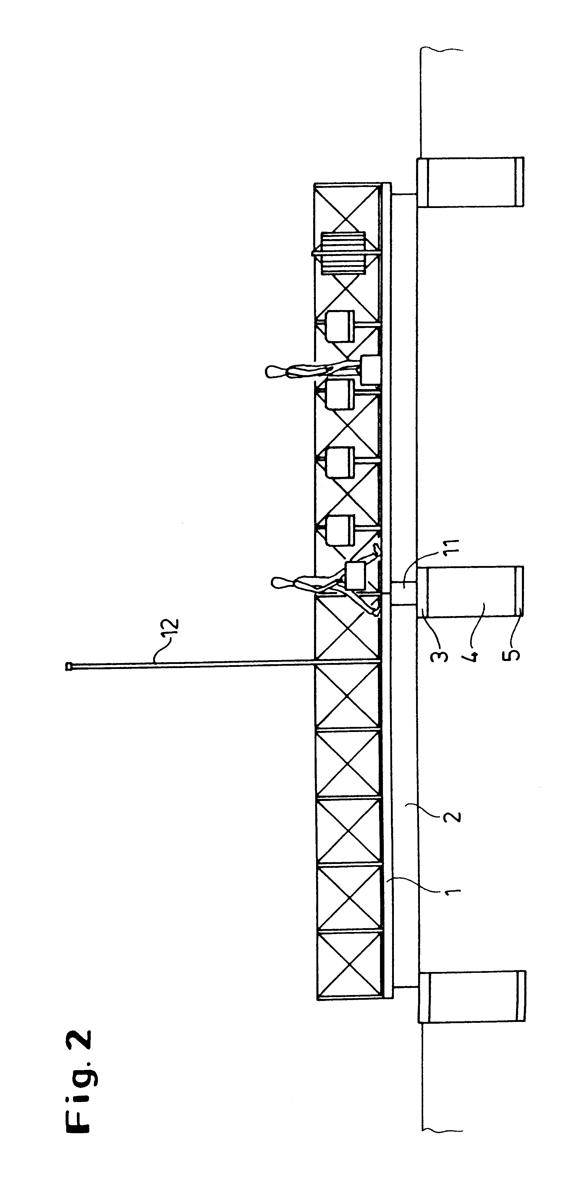
Prefabricated kit for producing a station platform which is variable in its dimensions, in which platform slabs (1) are laid on foundations (4) with interposition of spacer elements (3). The spacer elements (3) can be replaced without damaging the other construction elements (1, 3, 4). The platform slabs (1) may be arranged in various horizontal positions above the foundations (4) in order to compensate for horizontal differences in size in relation to the axis of the track.

Description

1. Field of the InventionThe present invention relates to a variable station platform with one or more platform slabs.2. Description of the Related ArtIn conventional construction, station platforms are described as a stationary structure. Such station platforms are produced on the precondition that they should remain unchanged for many generations. However, static structures of this kind no longer meet the requirements of modern rail traffic. On the one hand, they are inflexible with regard to requirements emanating from new technical developments. On the other hand, they do not provide the possibility of carrying out unavoidable corrections relating to dimensions and spacings on the structure at a later time in a straightforward and cost-effective manner. Under the modern requirements for comfort and safety, it is no longer acceptable to tolerate such deviations without correction. Moreover, the conventional station platforms are to be criticized from a current standpoint for the ...

Claims


Application Information

Patent Timeline
IPC IPC(8): E01F1/00
CPCE01F1/00
Inventor EDELMANN, HORST
Owner HERING
Learn More