Ball screw having spacers

a technology of ball screw and spacer, which is applied in the direction of gearing, mechanical control devices, hoisting equipment, etc., can solve the problems of increasing dynamic friction, early fracture, and not yet putting into tangible form the effect of 6.5 effective turns of the ball screw

Inactive Publication Date: 2001-01-23
TSUBAKI NAKASHIMA
View PDF12 Cites 81 Cited by
  • Summary
  • Abstract
  • Description
  • Claims
  • Application Information

AI Technical Summary

Problems solved by technology

However, such a ball screw having 6.5 effective turns is not yet put into a tangible form because of the reasons mentioned below.
Though the degree depends on the machined accuracy and so on of the ball screw groove, it has been experienced that a normal feeding operation with more than 120 balls installed in one circuit of a ball nut brings about an increase in dynamic friction torque caused by the adjoining balls rotating in the same direction and pressing against each other, a ball clogging phenomenon, an early wear and a ball slipping phenomenon, which may cause an early fracture.
Further, since a manufacturing cost of the end cap itself is high, above ball circulation mechanism is seldom used except for a fast lead or an ultra-fast lead which are suitable for high-speed requirements.
Even though the number of balls in one circuit is limited to 120 or less, however, it was experienced during a reciprocating movement that an increase in friction torque during the reciprocation (hereafter called "reciprocating friction torque") and a ball clogging phenomenon occurred.
Further, some of high-loading usage of the injection molding machine and so on require a ball screw to make a reciprocating movement.
(1) It was often impossible to adopt the method of making the shaft diameter of the screw shaft la...

Method used


Image

  • Ball screw having spacers
  • Ball screw having spacers
  • Ball screw having spacers

Examples


second embodiment

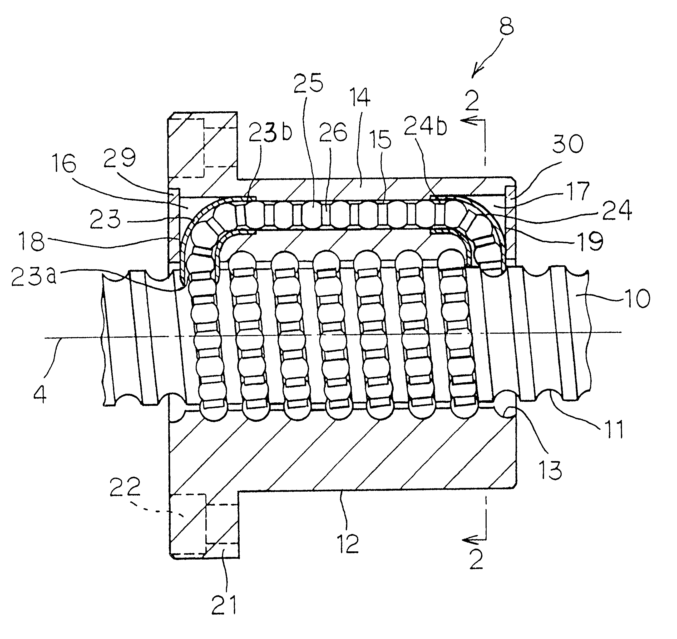
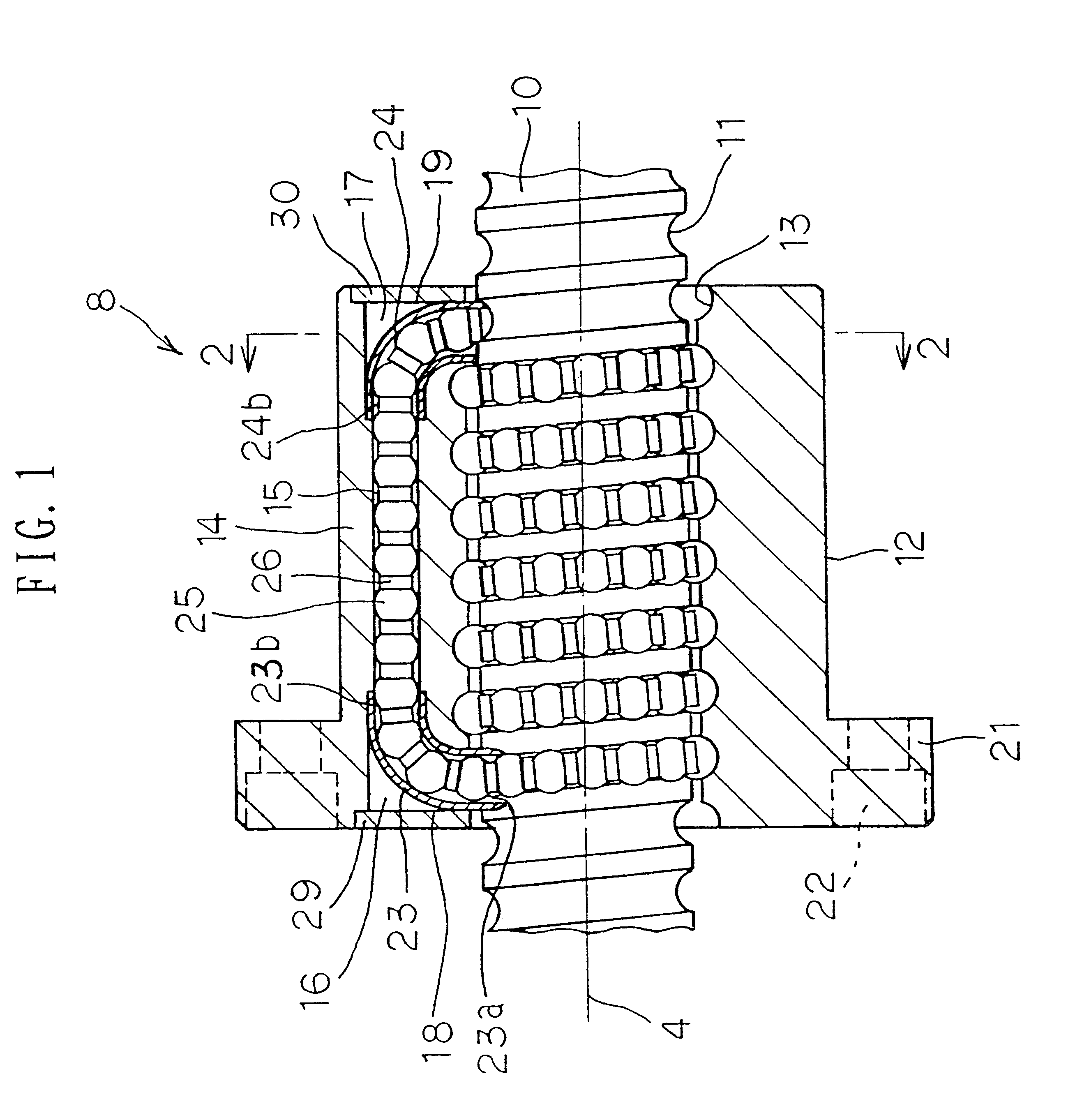
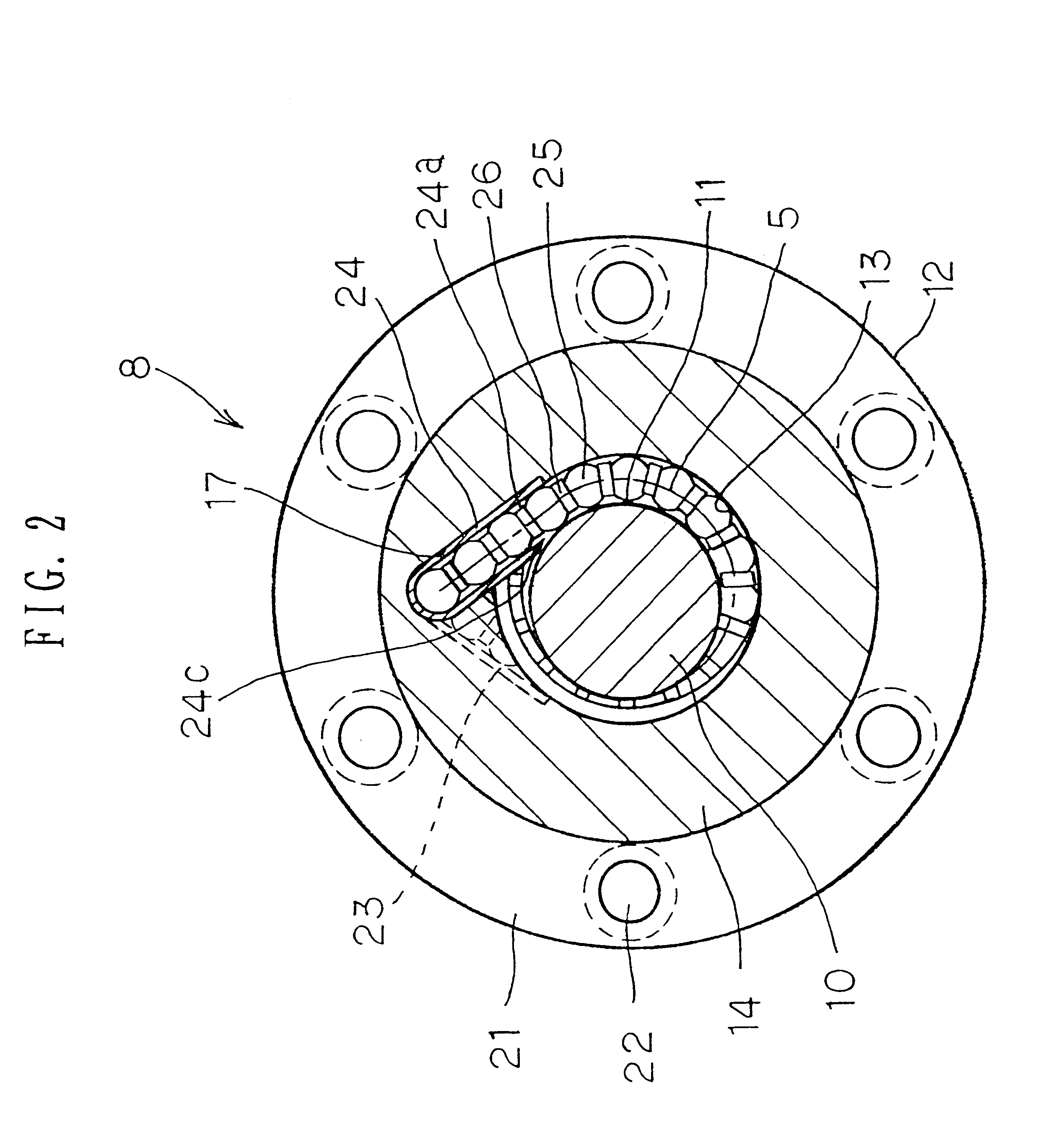
The second embodiment is applied when the thick wall part 14 of the ball nut 12 is not thick enough for a through hole 15 to be provided therein.

A flat notch surface 36 is formed on an outer peripheral surface of the ball nut 12. On the notch surface 36, a straight tube 38 is mounted by a tube retaining member 41 and a set screw 42 in parallel to an axial line 4 of the ball nut 12. Then, a circulation mechanism of the ball 25 and the spacer 26 is formed when the both open ends 38a, 38b of the tube 38 are each in communication with the open ends 23b, 24b of the adapters 23, 24.

first embodiment

Since its operation is the same as the one in the first embodiment, the description thereof is omitted.

FIG. 13 shows a modified form of the tube 38. On both open ends 38a, 38b of the tube 38, there is a protrusion (or a recess) 39, 40 formed respectively. By engaging this protrusion (or recess) 39, 40 with the recess (or protrusion) 23d, 24d formed on the open ends 23b, 24b of the adapters, the tube 38 and adapters 23, 24 are connected to be in communication reliably.

Further, in this second embodiment, followings are also applicable:

1) Instead of on the flat notch surface 36 provided on the outer peripheral surface of the ball nut 12, the tube 38 may be mounted directly on the outer peripheral surface of the ball nut 12.

2) Though the tube 38 and the adapters 23, 24 are formed as separate bodies, each end of the tube may be bent to be formed into a portion which takes place of the adapter.


PUM


Abstract

Spacers 26 each of which has a concave surface 27 complementary to the spherical surface of a ball 25 at each end thereof are disposed at areas between the adjacent balls 25, 25. A ball circulation mechanism comprises; a through hole 15 which extends in parallel to an axial line 4 of the ball nut 12 inside a thick wall part 14 of the ball nut 12; and adapters 23, 24 having open ends 23a, 24a provided with tongue portions 23c, 24c for scooping up or returning balls 25 between a ball screw groove 11 of a ball shaft 10 and a ball screw groove 13 of the ball nut 12, and the other open ends 23b, 24b being connected to be in communication with the through hole 15, and each adapter being fitted into recesses 16, 17 provided on both axial ends in the thick wall part 14 of the ball nut 12. Therefore, there is no need of upsizing a ball screw, and thus a compact ball screw which has a high load-carrying capacity and is suitable for a reciprocating movement can be provided.

Description

The present invention relates to a ball screw used for various feed mechanisms. More particularly, it relates to a ball screw which has a high load-carrying capacity and is suitable for repetitive back-and-forth operations with minute feedings, namely, reciprocating movements.PRIOR ARTThere is a ball screw known which comprises a screw shaft including a ball screw groove on the outer peripheral surface thereof., a ball nut including on the inner peripheral surface thereof another ball screw groove opposed to the ball screw groove, and a plurality of balls installed between the both ball screw grooves and adapted to circulate by a ball circulation mechanism provided in the ball nut.For example, in U.S. Pat. No. 2,995,947, there is disclosed a ball screw in which a "return tube" is used as a ball circulation mechanism and of which number of effective turns is 6.5 and number of circuit(s) is one. However, such a ball screw having 6.5 effective turns is not yet put into a tangible form ...

Claims


Application Information

Patent Timeline
IPC IPC(8): F16C19/02F16H25/22F16C19/20F16C33/37
CPCF16C33/3706F16H25/2238F16H25/2219F16H2025/2242Y10T74/19772Y10T74/19749Y10T74/20594
Inventor MISU, HIROSHI
Owner TSUBAKI NAKASHIMA
Why Eureka
Try Eureka