High-speed logarithmic photo-detector

a logarithmic and photo-detector technology, applied in the field of photo-detectors, can solve the problems of high cost of photomultiplier tubes, damage, and limited useful dynamic range of subsequent electronics

Inactive Publication Date: 2001-01-23
KLA TENCOR TECH CORP
View PDF2 Cites 32 Cited by
  • Summary
  • Abstract
  • Description
  • Claims
  • Application Information

AI Technical Summary

Problems solved by technology

Even though photodiodes have excellent dynamic range (they are linear over up to 14 orders of magnitude) their output is proportional to the optical signal, so in practice their useful dynamic range is quickly limited by subsequent electronics.
Photomultiplier tubes are expensive (typically $100 to over $1000), are subject to damage from overloading input signals, such as ordinary room light, and require a high voltage (typically 1000 Volts) to operate.
However, the large voltages involved make it difficult to change the gain quickly, due to parasitic capacitances and the large resistor values needed to limit power dissipation in the

Method used


Image

  • High-speed logarithmic photo-detector
  • High-speed logarithmic photo-detector
  • High-speed logarithmic photo-detector

Examples


Embodiment Construction

Those of ordinary skill in the art will realize that the following description of the present invention is illustrative only and not in any way limiting. Other embodiments of the invention will readily suggest themselves to such skilled persons.

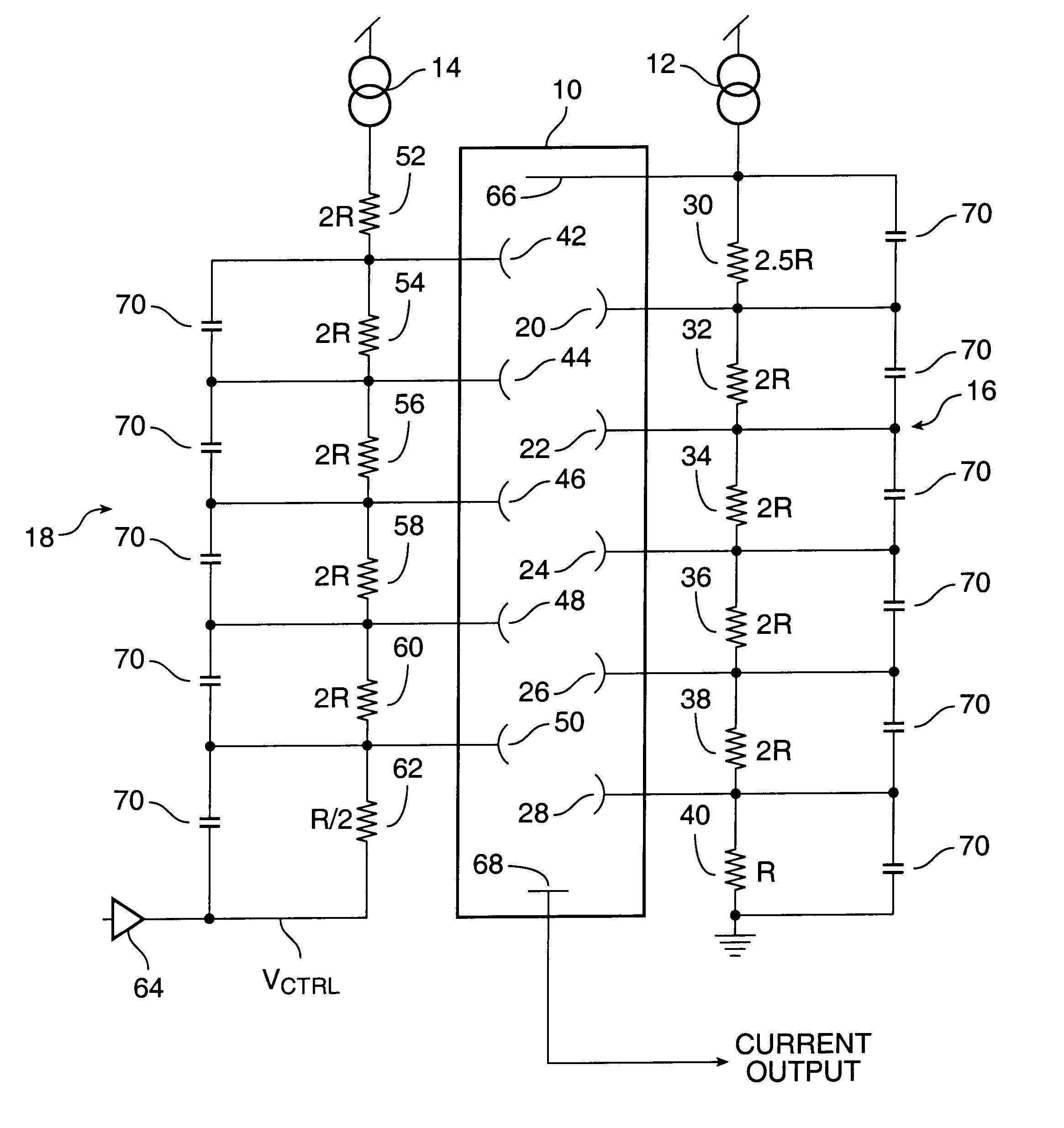
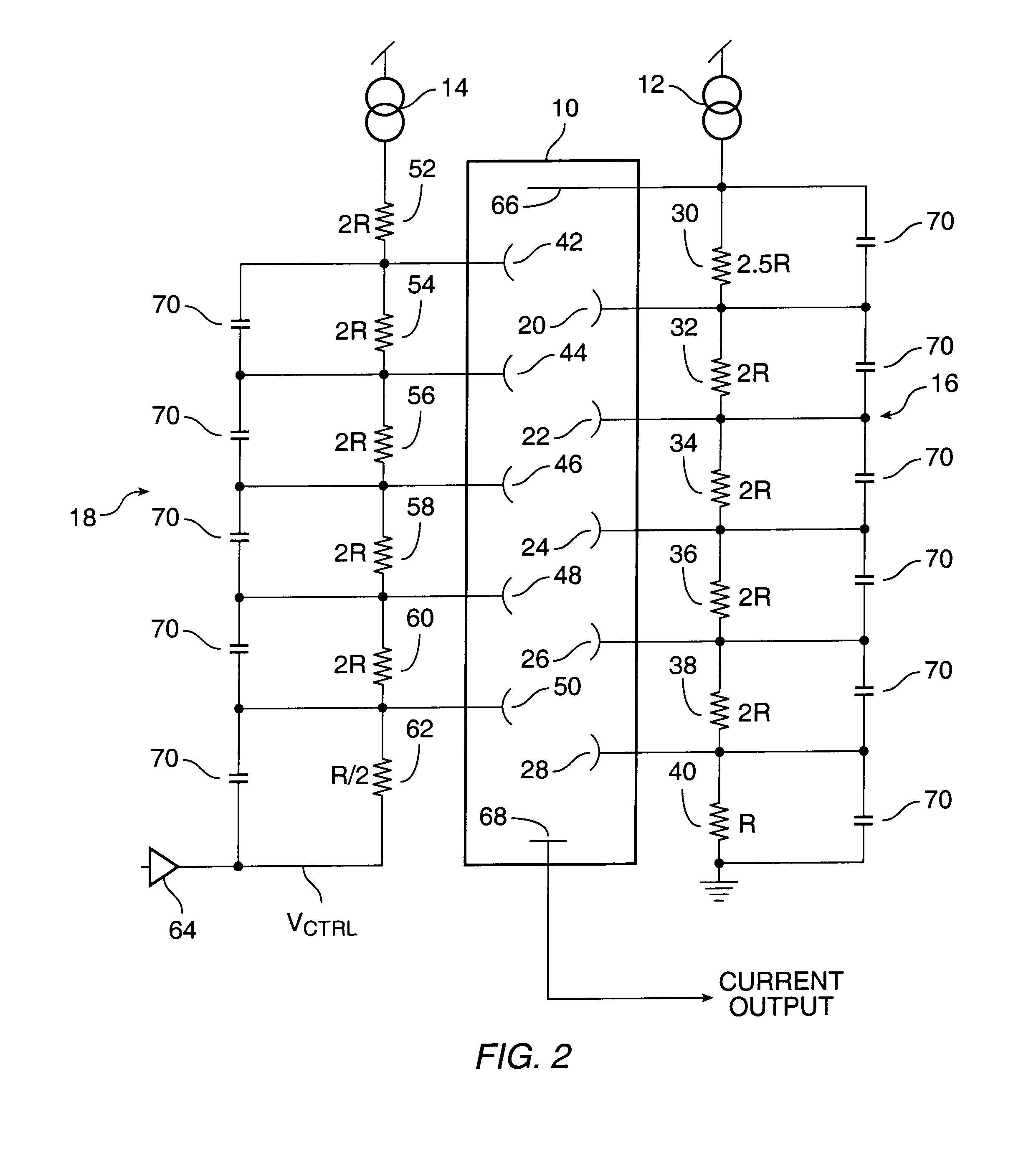
According to the present invention, apparatus and a method have been developed for rapidly and precisely controlling the gain of the photomultiplier tube. The photomultiplier tube is used with a high-speed feedback mechanism to continuously modulate the gain of the tube in response to the anode signal. The gain of the tube and the anode current are independently converted to ideal logarithms. These signals are then subtracted from one another (the log-space equivalent of division) to reconstruct a true logarithmic representation of the optical signal. By this method, the dynamic range of the photomultiplier tube can be extended to at least 6 orders of magnitude, for continuously varying signals with bandwidth of up to 25 MHz, and possible mor...


PUM


Abstract

According to the present invention, a photomultiplier tube is used with a high-speed feedback mechanism to continuously modulate the gain of the tube in response to the size of the input signal. The gain of the tube and the anode current are independently converted to ideal logarithms. These signals are then subtracted from one another to reconstruct a true logarithmic representation of the optical signal. This log-light-level signal has a higher dynamic range and faster temporal response than has previously been achieved by other methods.

Description

1. Field of the InventionThe present invention relates to photodetectors. More particularly, the present invention relates to photodetection systems employing photomultiplier tubes.2. The Prior ArtOptical sensing is the process of converting optical signals (photons) into electrical signals (electrons). In most applications, where the optical signals are large, or the temporal frequencies are low, this is done using solid state devices known as Photodiodes. Photodiodes are inexpensive (typically $1 to $30) and simple to use. They have a high dynamic range, and can be very fast when the light levels are large.For signals which are too dim to see, photodiodes become much slower, due to the relatively high capacitance of the diode and the small currents generated by the dim signals. Even though photodiodes have excellent dynamic range (they are linear over up to 14 orders of magnitude) their output is proportional to the optical signal, so in practice their useful dynamic range is quic...

Claims


Application Information

Patent Timeline
IPC IPC(8): G01J1/44H01J43/30H01J43/00G01J1/42H01J43/02
CPCG01J1/44H01J43/18H01J43/30
Inventor WOLF, RALPH C.
Owner KLA TENCOR TECH CORP
Why Eureka
Try Eureka