Methods and apparatus for the closed loop control of magnetron current

a closed loop, magnetron technology, applied in the direction of electric variable regulation, process and machine control, instruments, etc., can solve the problems of inability to control the operation of the magnetron within its optimum operating range, the sensitivity of the magnetron output power to the magnetron voltage may be undetectedly low, and the difficulty of prior art system control of the magnetron curren

Inactive Publication Date: 2001-01-23
HONEYWELL INC
View PDF10 Cites 16 Cited by
  • Summary
  • Abstract
  • Description
  • Claims
  • Application Information

AI Technical Summary

Problems solved by technology

Attempts to control magnetron operation within its optimum operating range have met with limited success.
This is due in part to the fact that although it may be possible to control magnetron voltage, the sensitivity of the magnetron output power to the magnetron voltage may...

Method used


Image

  • Methods and apparatus for the closed loop control of magnetron current
  • Methods and apparatus for the closed loop control of magnetron current
  • Methods and apparatus for the closed loop control of magnetron current

Examples


Embodiment Construction

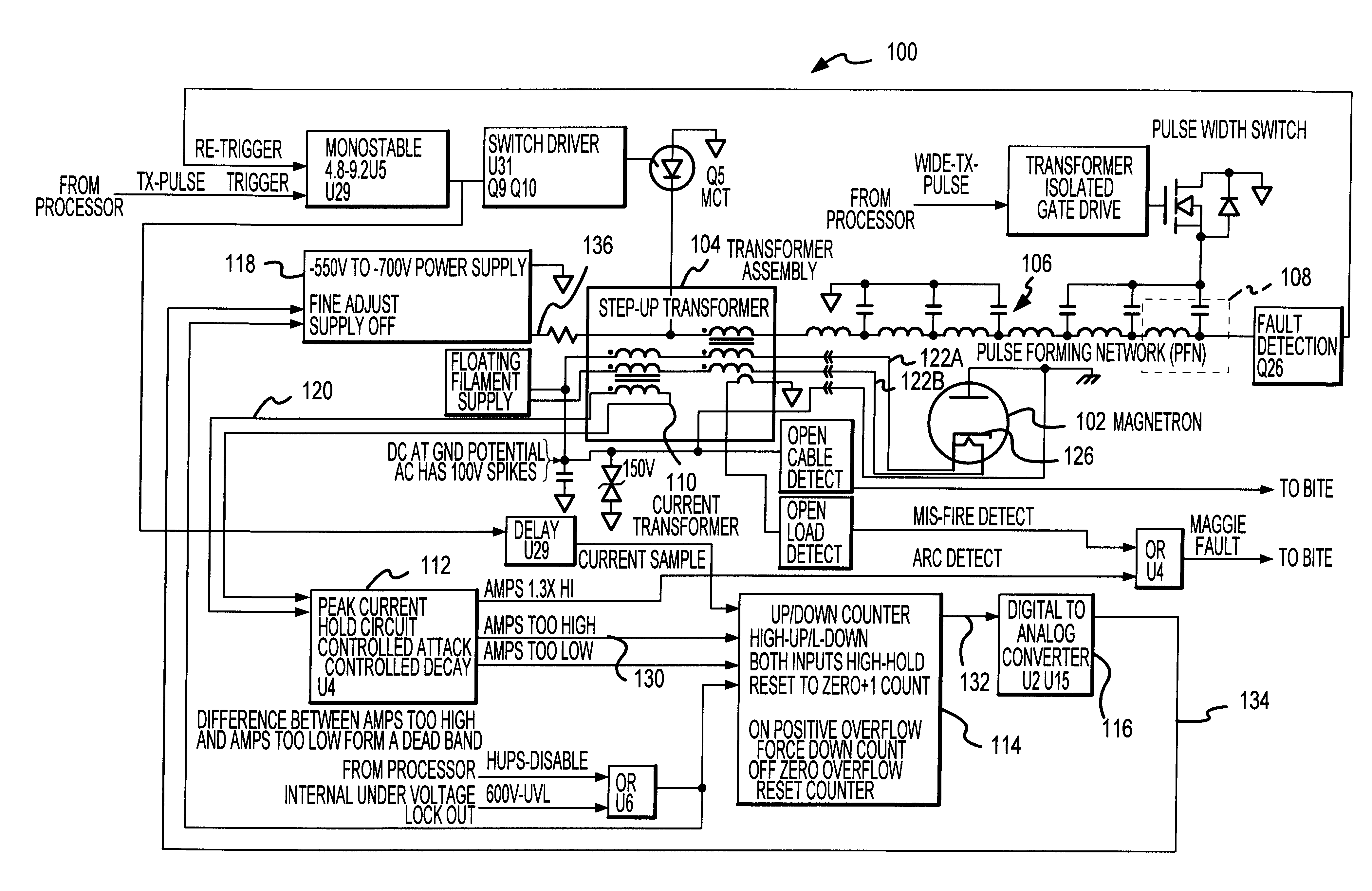
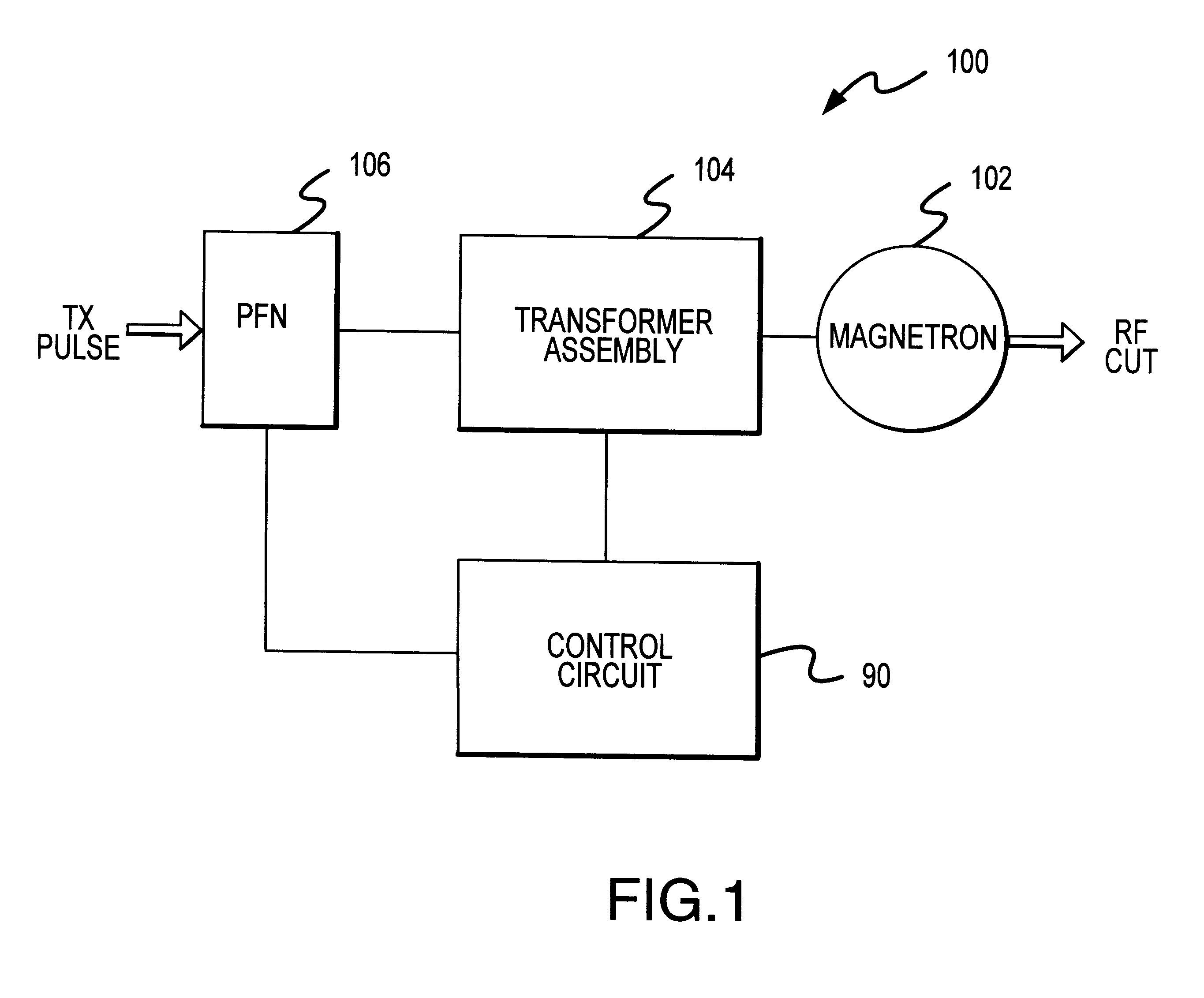
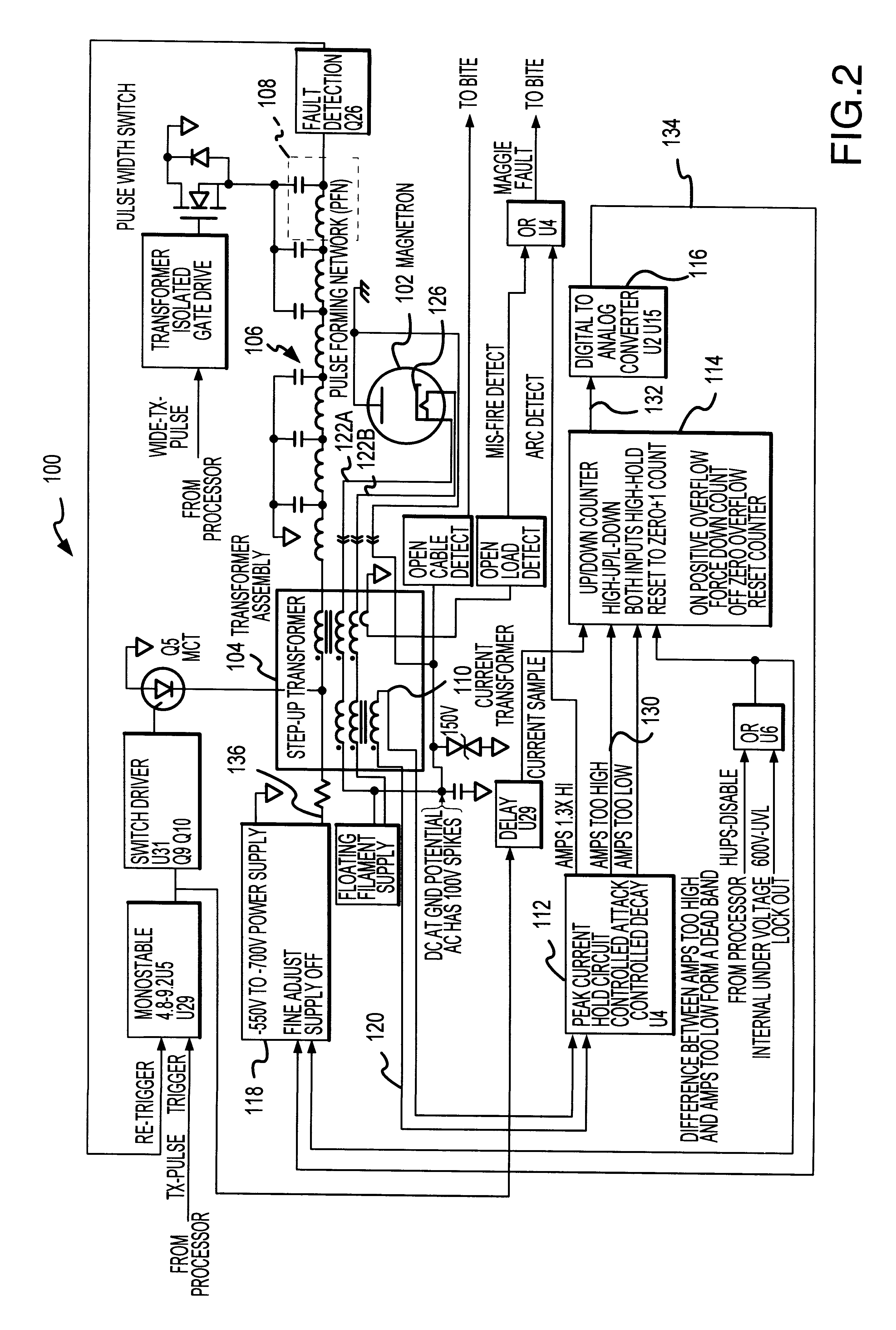
The load that a magnetron presents to its modulator may be modeled as a zener diode. In particular, a typical magnetron draws capacitive current up to a certain voltage and thereafter presents a dynamic load impedance to the modulator. Optimum magnetron performance requires that the current through the magnetron be closely trimmed to the desired operating point, for example in the range of 5%. FIG. 1 is a general block diagram representation of a control system 100 configured to control the magnetron current applied to a magnetron 102. Control system 100 may be utilized to control the RF output of magnetron 102 at a suitable level. Control system 100 generally includes a control circuit 90 coupled between a transformer assembly 104 and a pulse forming network (PFN) 106. Magnetron 102 receives a drive current from transformer assembly 104 in a manner known to those skilled in the art.

Control circuit 90 is adapted to monitor an electrical parameter (e.g., magnetron current) of transfo...


PUM


Abstract

A fault-tolerant control system facilitates the closed loop control of a magnetron. The control system includes a transformer assembly for applying peak current to a magnetron, a pulse-forming network that conditions a transmit pulse, and a control circuit for adjusting the peak current applied to the magnetron. The control circuit includes a sample and hold circuit for comparing a signal representative of a detected peak current to a desired peak current level. The sample and hold circuit is coupled to a digital up/down counter circuit, and the output of the counter circuit is utilized to adjust the charge voltage of the pulse-forming network.

Description

1. Field of the InventionThe present invention relates, generally, to a technique for controlling the RF output of a magnetron of a type employing a pulse-forming network to generate output pulses and, more particularly, to a closed-loop control system for controlling peak current through the magnetron using a peak current sense in a feedback loop.2. Description of the Related ArtThe use of magnetrons in radar systems is generally well known. Such radar systems are extensively used in military applications for detecting aircraft, projectiles, and the like. Magnetron-based radar systems are also routinely employed in weather systems to detect rain clouds, turbulence, and the like.Presently known magnetrons typically comprise a diode encased in a vacuum tube. The diode essentially comprises a cathode and an anode, wherein a current source is fed to the cathode plate by a compatible current source. A pulse-forming network (PFN) may be utilized to condition a transmit pulse produced by ...

Claims


Application Information

Patent Timeline
IPC IPC(8): G05F1/66G01S7/28G01S7/282H01J23/34
CPCG05F1/66G01S7/282H01J2225/50
Inventor SCHWERMAN, PAUL WILLIAM
Owner HONEYWELL INC
Why Eureka
Try Eureka