Eureka AIR delivers breakthrough ideas for toughest innovation challenges, trusted by R&D personnel around the world.

Load carrying structure having variable flexibility

a load carrying structure and variable flexibility technology, applied in the direction of marine propulsion, vessel parts, vessel construction, etc., can solve the problems of large total number of components interacting in rather complicated ways, complicated joint members and locking devices,

Inactive Publication Date: 2001-02-06
INST FUER VERBUNDWERKSTOFFE GMBH +1
View PDF11 Cites 93 Cited by
  • Summary
  • Abstract
  • Description
  • Claims
  • Application Information

AI Technical Summary

Benefits of technology

The invention provides a variably flexible structure with an integrated selective releasing and locking function, in a very simple manner. When the heating arrangement heats the thermoplastic material to a temperature at or above the softening temperature, the rigid condition is released or overcome, so that the thermoplastic material element and the overall load carrying structure becomes flexibly movable into a new position or configuration. After the heating arrangement is switched off and the thermoplastic material cools down to the normal operating temperature below the softening temperature, the thermoplastic material again becomes rigid, whereby the new position or configuration is rigidly fixed. The invention achieves this without requiring any additional locking mechanism.
By softening the thermoplastic material at its softening temperature, the stiffness of the load carrying structure can thereby be reduced as required in order to then be able to deform the structure or to slidingly or otherwise displace the interconnected components relative to each other, while exerting only a relatively small force on the structure. Then, by cooling the thermoplastic material to a temperature below the softening temperature, the stiffness will again be increased, whereby the deformed or newly established geometry can be maintained without any further or permanent application of force. In this manner, the displaced components can again be locked rigidly to each other in the newly established position, without requiring a complicated locking mechanism. This process can be carried out reversibly and repeatedly practically as often as desired over the life of the structure.
In view of the above considerations, it is apparent that the invention provides a load carrying structure with a lightweight construction and with an integrated joint function, whereby the joint can be selectively flexibly released or locked, depending on whether the thermoplastic material is heated up to at least its softening temperature by switching on the heating arrangement or is allowed to cool to below its softening temperature by switching off the heating arrangement. The load carrying structure according to the invention is thus broadly applicable in many fields, and especially in the fields of motor vehicle construction and aircraft construction wherever a joint or structure having variable flexibility is needed.

Problems solved by technology

As a result, known load carrying structures that are selectively adjustable to be rigid or flexible thus require complicated joint members and locking devices, and a rather great total number of components interacting in rather complicated ways.
This is especially disadvantageous in structures that are to be built according to lightweight construction techniques, for which the primary goal is naturally a minimization of the overall weight together with a reduction of the number of components.

Method used


Image

  • Load carrying structure having variable flexibility
  • Load carrying structure having variable flexibility

Examples


Embodiment Construction

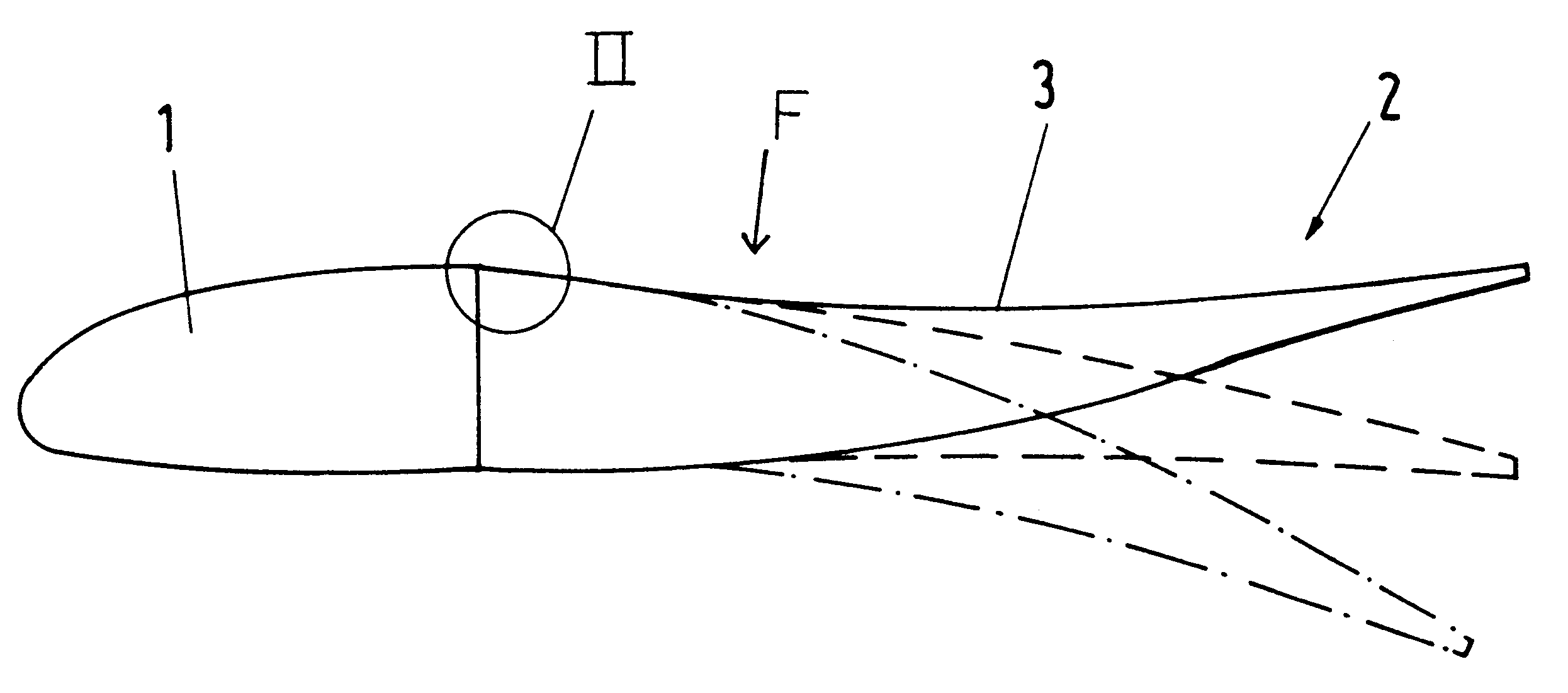
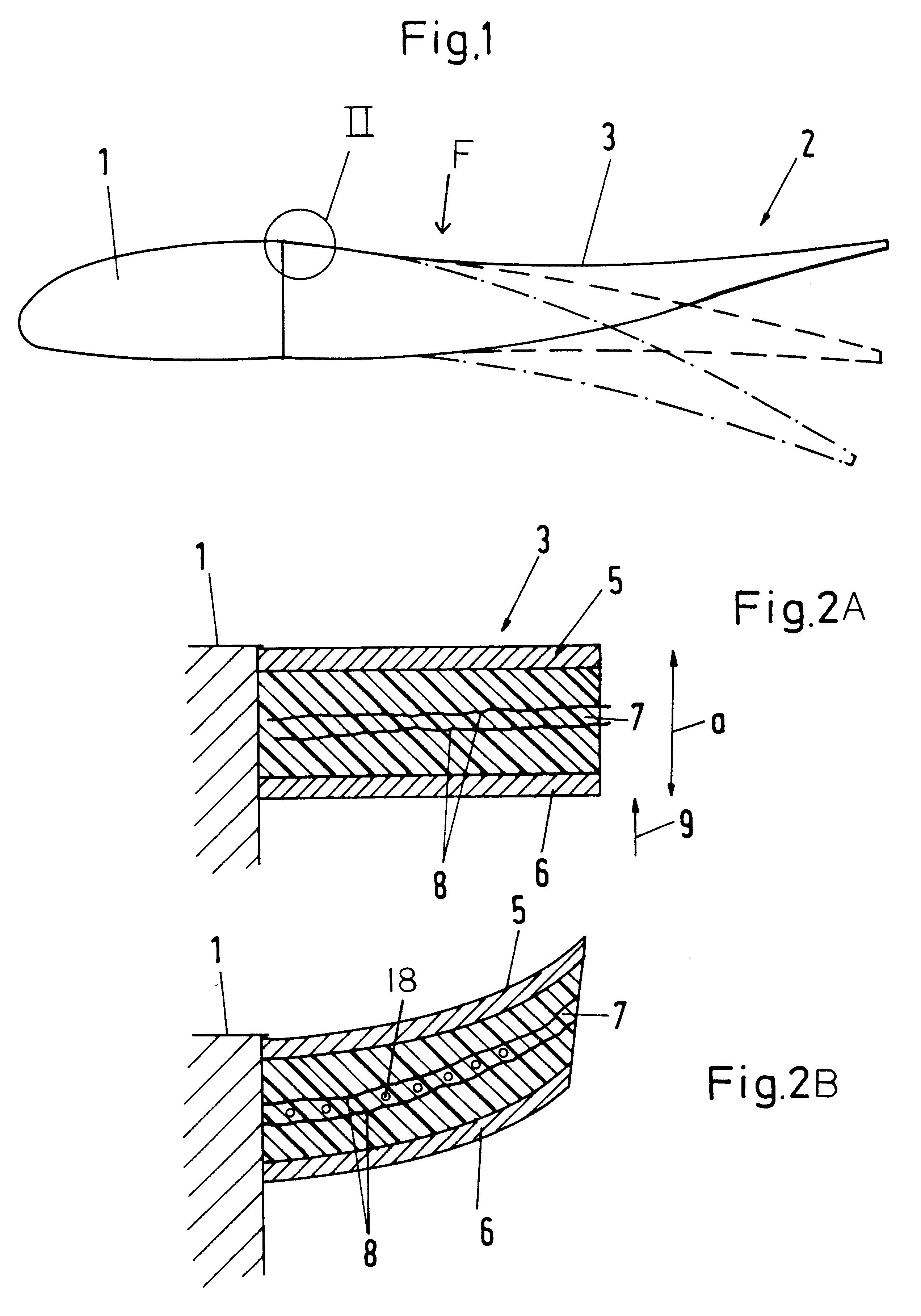
As shown in FIG. 1, the landing flap F of an aircraft wing comprises a forward portion 1 and a trailing edge portion 2 joined onto the forward portion in an aerodynamically streamlined manner. While the forward portion 1 may be substantially rigid, it is desired that the trailing edge portion 2 should be selectively flexibly deflectable both upward and downward relative to the forward portion. To achieve this, the trailing edge portion 2 comprises a cover skin 3 that is secured to the forward portion 1 at the upper surface of the flap F. The bottom cover skin of the trailing edge portion 2 may or may not be fixedly connected to the forward portion 1 so as to respectively form a rigid connection between the two portions 1 and 2 or a selectively flexible hinge joint connection between the two portions 1 and 2 in the detail area II, as desired.

In any event, the trailing edge portion 2 is so constructed that it can be bendingly or flexibly deflected between a maximum upward deflected po...


PUM


Abstract

A load carrying structure having a selectively rigid or flexible characteristic includes a thermoplastic material (7) having a softening temperature above the operating temperature range of the load carrying structure, and a heating arrangement (8) provided to selectively heat the thermoplastic material to above its softening temperature. During normal operation, the thermoplastic material is in a rigid state and the overall load carrying structure is rigid to the prevailing loads. By activating the heating arrangement to heat the thermoplastic material to at least its softening temperature, the thermoplastic material and therewith the load carrying structure becomes flexible so that it may be deformed to a different configuration by applying a deforming load. Once the desired deformed configuration is achieved, the heating arrangement is deactivated, and the thermoplastic material is allowed to cool below its softening temperature so that it once again becomes rigid and rigidly fixes the new deformed configuration. The deforming force may be applied by any actuating mechanism, or for example by arranging shape memory alloys in connection with the thermoplastic material.

Description

PRIORITY CLAIMThis application is based on and claims the priority under 35 U.S.C. .sctn.119 of German Patent Application 197 42 314.0, filed on Sep. 25, 1997, the entire disclosure of which is incorporated herein by reference.The invention relates to a load carrying structure that has a variable flexibility, i.e. that can be selectively adjusted or actuated to be relatively rigid or relatively flexible or deformable, as needed at any time.BACKGROUND INFORMATIONAccording to the state of the art, structural components that are to be connected together in a manner that is selectively rigid or flexibly movable are typically connected by a joint or hinge structure that is, in itself, flexible. In order to provide the necessary rigidity in addition to the necessary flexibility, the known structures further include a locking device that can be selectively locked or released, so as to selectively lock the flexible joint in one or more desired fixed positions, or alternatively release the j...

Claims


Application Information

Patent Timeline
IPC IPC(8): B63B39/00B63B1/16B64C27/615B63B39/06B64C3/00B63B1/24B64C3/48B64C27/00
CPCB63B1/248B63B39/06B64C3/48B64C27/615B64C2027/7288Y02T50/34Y02T50/30B64C3/38
Inventor MARTIN, WILLISIEGLING, HANS-FRIEDRICHKUHN, MARCELHIMMEL, NORBERT
Owner INST FUER VERBUNDWERKSTOFFE GMBH
Why Eureka
Eureka Blog
Learn More