Slurry pump control system

a control system and slurry technology, applied in the direction of lapping machines, manufacturing tools, transportation and packaging, etc., can solve the problems of high removal rate, large number of unacceptable finished wafers or circuits, and high degradation resistance of slurry used for polishing

Inactive Publication Date: 2001-02-06
REVASUM INC +1
View PDF11 Cites 38 Cited by
  • Summary
  • Abstract
  • Description
  • Claims
  • Application Information

AI Technical Summary

Problems solved by technology

In particular, unreliable slurry flow rates cause fluctuations in removal rates and a large number of unacceptable finished wafers or circuits.
The slurry used for polishing is sensitive to degradation by the components in the slurry flow path.
Whenever the slurry is subject to shear forces created by intrusive mechanical components such as pump impellers, pressure gauge taps, or flow meter vanes, its abrasive particles have tendency to agglomerate.
This agglomeration results in uneven polishing, scratching, and other defects in the polished surface.
However, flow rate is often measured with vaned flow meters or other intrusive and shear creating flow meters which rely of the insertion of physical structures into the slurry flow (any agglomeration is tolerated, and results in lower reliability and yield of the system).

Method used


Image

  • Slurry pump control system
  • Slurry pump control system
  • Slurry pump control system

Examples


Embodiment Construction

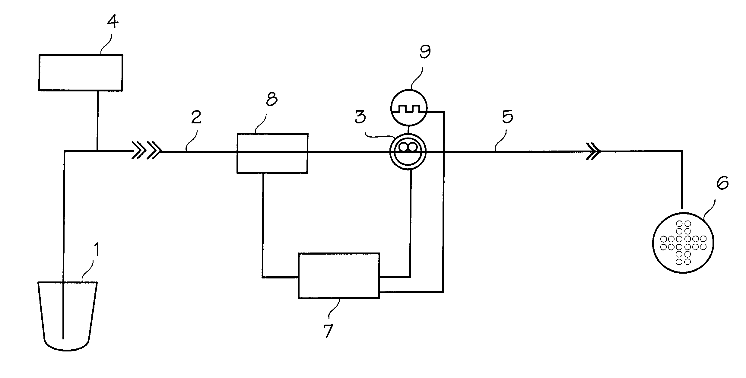
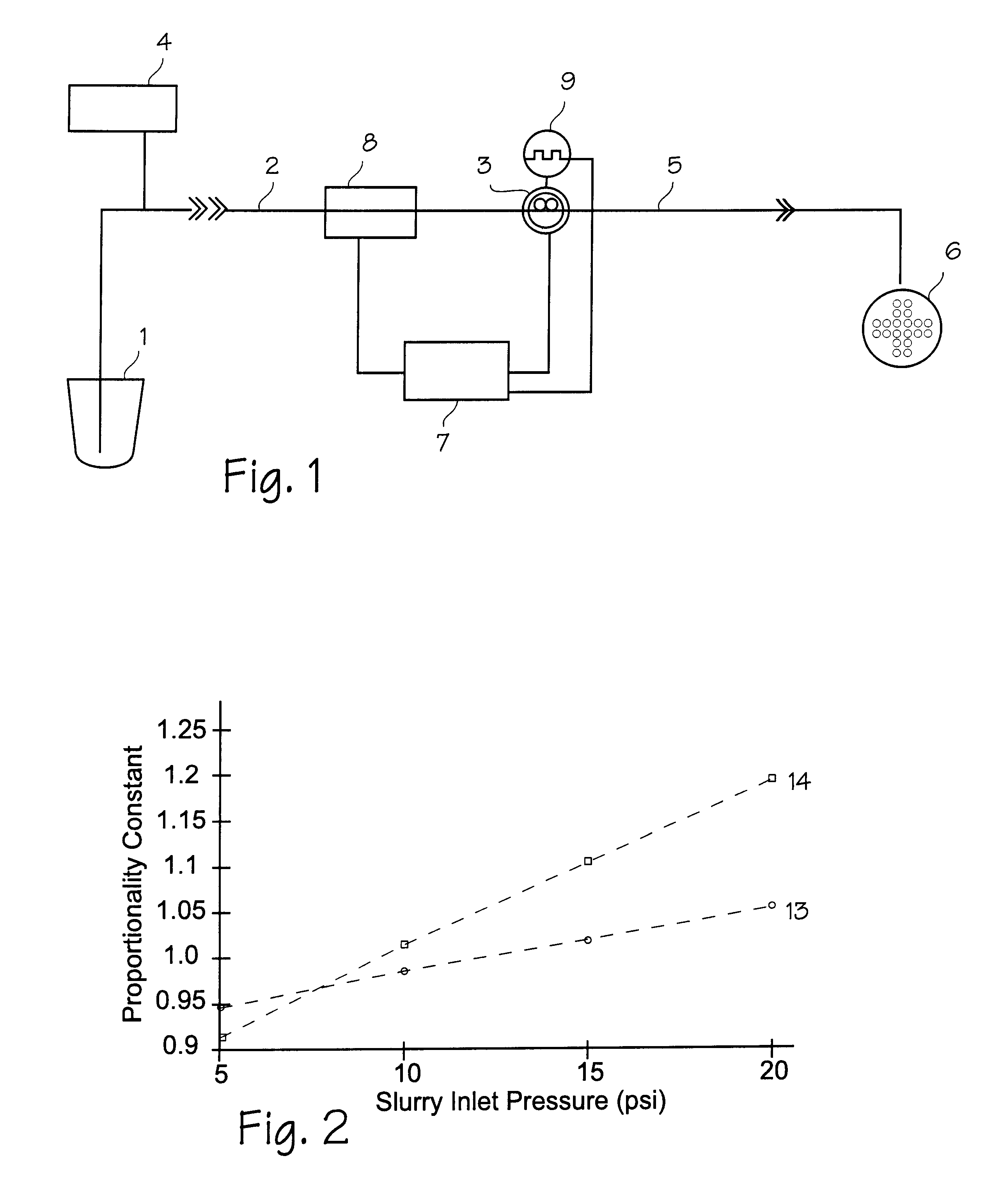
FIG. 1 illustrates the elements of a slurry supply system modified to monitor pump inlet pressure and use the sensed pressure to control the pump (pump speed feedback is also used). The slurry supply tank 1 provides pressurized slurry to the slurry supply inlet piping 2 of the motor operated slurry pump 3 (the pump may also be supplied by a de-ionized water source 4 for supply of pure water, or by both a slurry source and a de-ionized water supply.). The pump outlet 5 provides slurry onto the polishing pad assembly 6. The slurry pump is controlled by the pump controller 7. On the inlet piping, a pressure sensor 8 senses the pressure of the slurry (or whatever fluid is required) in the inlet to the pump and sends corresponding electrical signals representative of the slurry pump inlet pressure to the pump controller 7. The pump controller may be set by an operator to maintain a specified flow rate, in the range of 0-500 ml / min. The pump controller uses the specified flow rate, the se...


PUM

PropertyMeasurementUnit
flow rateaaaaaaaaaa
speedaaaaaaaaaa
pressureaaaaaaaaaa

Abstract

A CMP slurry pumping system which uses the slurry pump inlet pressure as input to the pump controller, and adjusts pump speed to account for variations in inlet pressure.

Description

FIELD OF THE INVENTIONSThe devices and methods described below relate to the fields of chemical mechanical polishing and control of slurry flow rates. The devices and methods may also be used in the grinding and polishing of wafers for the electronic materials and data storage industries.BACKGROUND OF THE INVENTIONSChemical mechanical polishing (CMP) is a process for very finely polishing surfaces under precisely controlled conditions. In applications such as polishing wafers and integrated circuits, the process is used to remove a few angstroms of material from an integrated circuit layer, removing a precise thickness from the surface and leaving a perfectly flat surface. The surface to be polished may be comprised of many materials, including various metals and silicates.To perform chemical mechanical polishing, a slurry comprising a suitable abrasive, a chemical agent which enhances the abrasion process, and water is pumped onto a set of polishing pads. The polishing pads are rot...

Claims


Application Information

Patent Timeline
Patent Type & Authority Patents(United States)
IPC IPC(8): B24B37/04B24B49/10B24B57/00B24B57/02
CPCB24B37/04B24B49/10B24B57/02Y10T137/0379
Inventor MELCER, CHRIS
Owner REVASUM INC
Why Eureka
Try Eureka