Hydraulic vehicle braking system

Inactive Publication Date: 2001-02-13
ROBERT BOSCH GMBH
View PDF12 Cites 36 Cited by
  • Summary
  • Abstract
  • Description
  • Claims
  • Application Information

AI Technical Summary

Benefits of technology

The hydraulic vehicle brake system, combines the keeping of air or gas, which is disposed in the hydraulic fluid of the external hydraulic energy source, out of the wheel brakes of the vehicle axle most strongly involved in the vehicle deceleration to the advantage of auxiliary brake operations with the simultaneous advantage that for example brake pressure changes in opposition can be carried out simultaneously in the left and right wheel brake of this vehicle axle, which is advantageous, particularly during a deceleration of the vehicle, when there is a simultaneous further use of the wheel brakes for automatically stabilizing the vehicle in relation to its vertical axis, for example when negotiating a curve. Left and right brake pressures, which are automatically adjusted differently, produce a yawing moment for the purpose of stabilizing the vehicle in relation to the vertical axis and also aid the driver in steering into and out of a curve. This kind of stabilization is called driving dynamics regulation, for example, and is extensively described in "Kraftfahrtechnisches Taschenbuch" [Handbook of Automotive Engineering] Bosch, 22nd edition, Dusseldorf, VDI-Verlag, 1995, ISBN 3-18-419122-2.
Advantageous improvements and updates of the hydraulic vehicle brake system disclosed are possible by means of the measures taken herein. The features of the system produce an exemplary embodiment that comprises the most frequent industrial application, namely a vehicle brake system for a passenger vehicle. In contrast, the exemplary embodiment can be the vehicle brake system of a truck, preferably one with double-tired rear wheels.
The system has an advantage that by means of actuating

Problems solved by technology

Because the air or gas could form compressible bubbles there and as a result, could jeopardize an auxiliary brake operation with the intrinsically very limited pump capacity of the master cylinder.

Method used


Image

  • Hydraulic vehicle braking system
  • Hydraulic vehicle braking system

Examples


Embodiment Construction

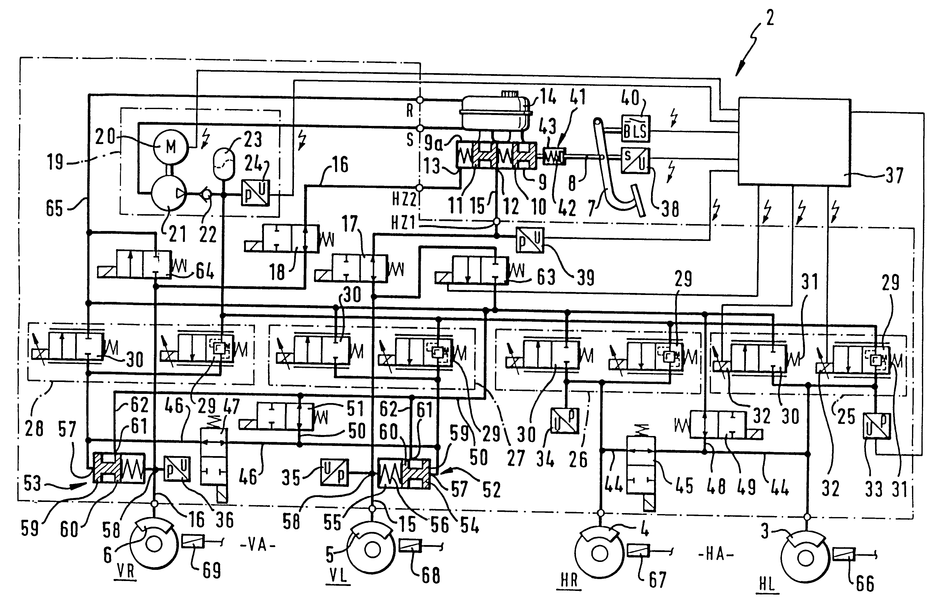
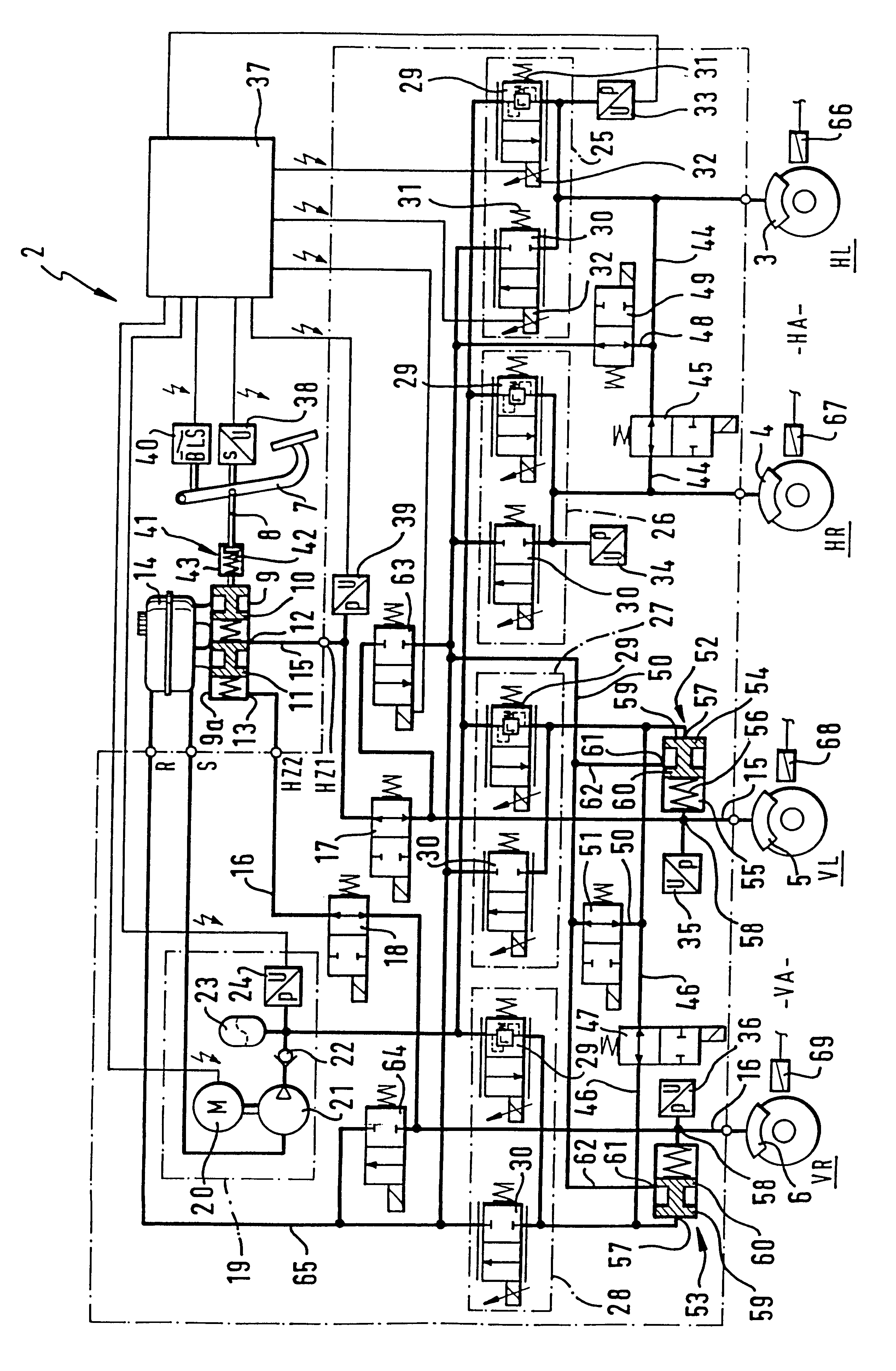
The hydraulic vehicle brake system 2 according to the invention and according to the FIGURE has hydraulically actuatable wheel brakes 3, 4, 5, and 6, a brake pedal 7 for executing auxiliary braking operations with muscle power, and a master cylinder 9, which is embodied with two circuits, the master cylinder can be actuated by way of a pedal rod 8 with the exertion of force on the brake pedal 7, and for this purpose, has a first master cylinder piston 10, a second master cylinder piston 11, a first master cylinder connection 12 associated with the first master cylinder piston 10, and a second master cylinder connection 13 associated with the second master cylinder piston 11, as well as a reservoir 14 for supplying fluid to the master cylinder. The master cylinder pistons 10 and 11 and the reservoir 14 including a housing 9a can be manufactured with structural features that can be inferred from the prior art. A first auxiliary brake line 15 leads from the first master cylinder connec...


PUM


Abstract

A hydraulic vehicle brake system in which normal service brake operation can be carried out by using external hydraulic energy, and in the event of a lack of external hydraulic energy, auxiliary brake operation by muscle power is possible, with a hydraulic transmission that comes from a master cylinder that can be actuated by means of the brake pedal. The external hydraulic energy is stored, for example, in an accumulator with a gas buffer, which can lead to a gas content in the hydraulic fluid for the service brake operation. The system includes a dual-circuit master cylinder associated with those wheel brakes of a vehicle axle that make a higher contribution to the vehicle deceleration and at the same time, cylinder / piston devices are installed between these wheel brakes and their associated service brake valves for the purpose of preventing hydraulic fluid from getting into these wheel brakes from the external energy source. The advantage is that neither gas nor air is carried into the wheel brakes where it could lead to the formation of bubbles in the event of a pressure drop and would be disadvantageous for an auxiliary brake operation by the master cylinder. The cylinder / piston devices increase the operational safety of the vehicle brake system when braking by muscle power.

Description

PRIOR ARTThe invention is based on a hydraulic vehicle brake system for a vehicle.FIGS. 1 and 2 of SAE Paper 96 0991 have disclosed two hydraulic vehicle brake systems with four wheel brakes for braking four wheels distributed on two vehicle axles by means of external hydraulic energy during normal brake operation, the service brake operation, and if need be, for example when there is a lack of or want of external hydraulic energy or electrical energy for controlling valves, for braking at least two wheels by means of muscle-powered energy in the so-called auxiliary brake operation. For the service brake operation, both vehicle brake systems have an external hydraulic energy source with a reservoir, pump, and pressure storage chamber, and between this external energy source and each of the four wheel brakes, have an electrically controllable brake valve device, which can be controlled at least indirectly as a function of a braking power signal from a braking power transmitter that c...

Claims


Application Information

Patent Timeline
IPC IPC(8): B60T8/40B60T13/68B60T13/10B60T13/16B60T8/36B60T8/00B60T8/44B60T8/88B60T13/12B60T13/66
CPCB60T8/3655B60T8/4086B60T13/168B60T13/686
Inventor JONNER, WOLF-DIETERENGFER, ORTWINVAN ZANTEN, ANTONBINDER, JURGENPFAU, MARTINSCHUNCK, EBERHARDTKAESSMANN, ANDREASHACHTEL, JUERGENGOTTWICK, ULRICHSCHUBERT, MICHAEL
Owner ROBERT BOSCH GMBH
Why Eureka
Try Eureka