Solid state resonance igniter for control of the number of high voltage pulses for hot restrike of discharge lamps

Inactive Publication Date: 2001-02-20
IREM
View PDF8 Cites 45 Cited by
  • Summary
  • Abstract
  • Description
  • Claims
  • Application Information

AI Technical Summary

Benefits of technology

The object of the present invention is to overcome the above-mentioned disadvantages and provide an igniter device in which it is possible to control the number and duration of high voltage pulses for triggering t

Problems solved by technology

In the cold state discharge lamps are perfect insulators since the gas filling the bulb has an insulating effect between the two electrodes, and the application of only the supply voltage (from 15 to 440 volts depending on the type of lamp) does not produce sufficient energy to strike the arc.
Although by now established and reliable, the ignition technique using igniters provided with spark gaps has intrinsic disadvantages, above all from the point of view of the control of the operation.
The discharge to the electrodes is a disruptive discharge having many harmonic components, and is therefore a source of electromagnetic and acoustic noise.
In a spark gap the electrical discharge across the terminals of the electrodes is, moreover, a phenomenon the instant of activation of which is d

Method used


Image

  • Solid state resonance igniter for control of the number of high voltage pulses for hot restrike of discharge lamps
  • Solid state resonance igniter for control of the number of high voltage pulses for hot restrike of discharge lamps
  • Solid state resonance igniter for control of the number of high voltage pulses for hot restrike of discharge lamps

Examples


Embodiment Construction

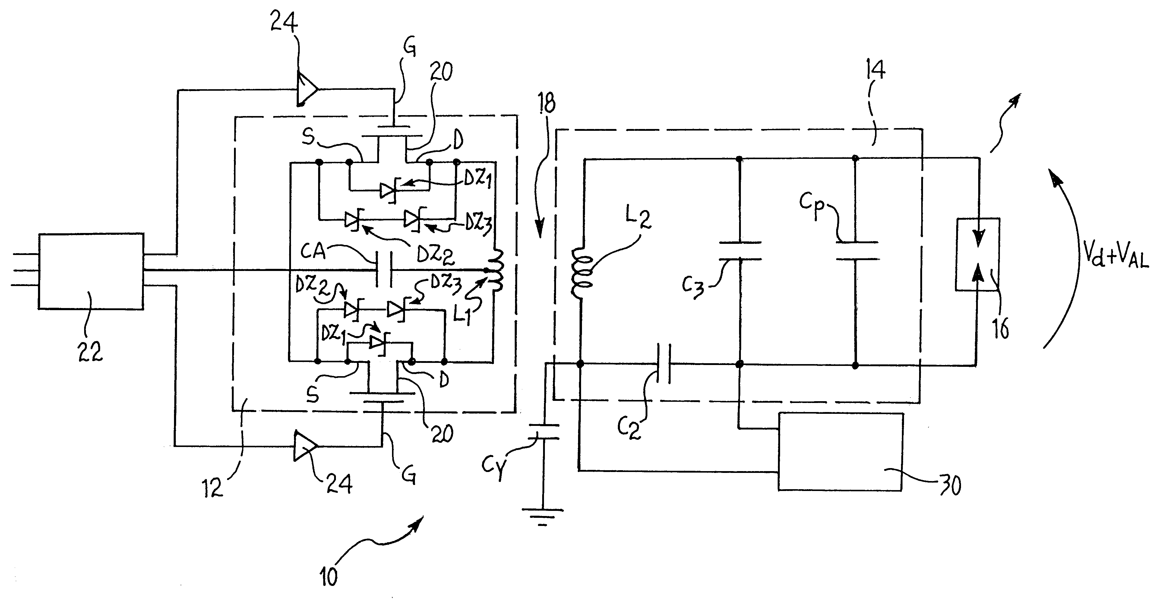
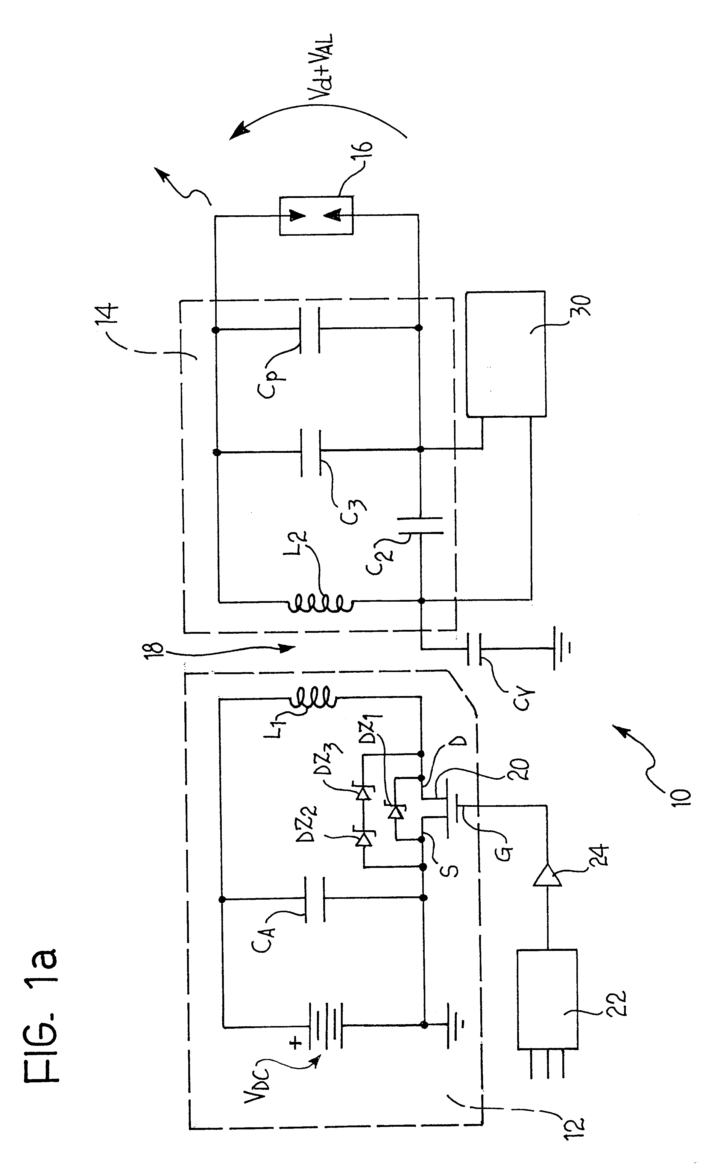
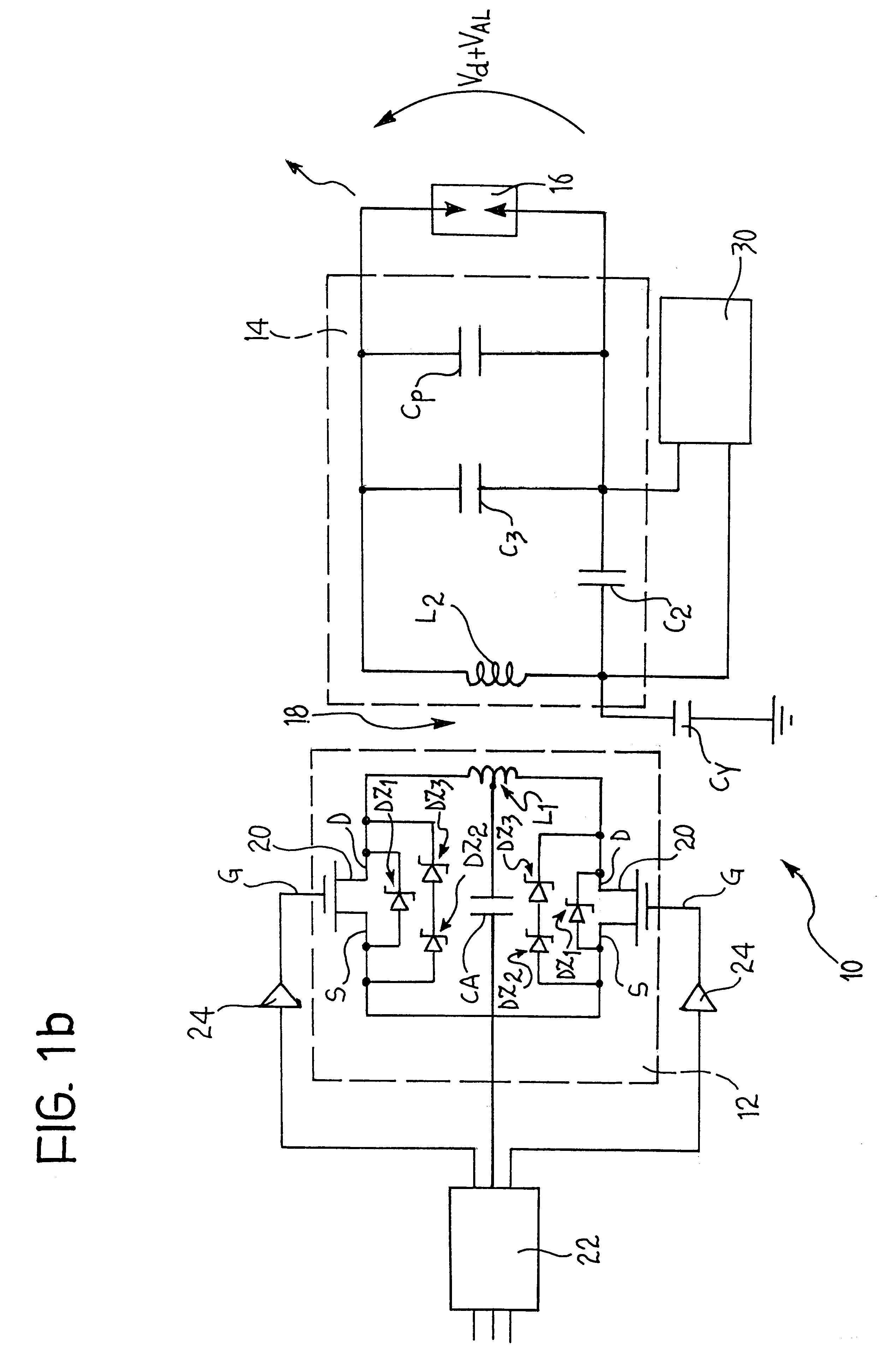
An igniter device according to the invention is indicated primary circuit 12 and a secondary circuit 14, this latter being directly coupled to a discharge lamp 16.

The primary circuit 12 has a dc voltage source V.sub.DC which may be directed from the main AC voltage or may be taken directly from a battery, and a starting capacitor C.sub.A in parallel with this source. The capacitor C.sub.A is also disposed in parallel with the primary winding L.sub.1 of a transformer 18 via an electronic switch 20. The switch 20 is a FET transistor, and in the currently preferred embodiment is formed as a MOSFET power transistor. The source electrode S of the transistor 20 is connected to a reference voltage such as the ground voltage, while the drain electrode D is directly coupled to a terminal of the primary winding L.sub.1 of the transformer. In parallel with the transistor 20 it is moreover possible to arrange a series of zener diodes DZ.sub.1 , DZ.sub.2, DZ.sub.3 for protection against over vol...


PUM


Abstract

A solid state igniter device for hot restrike of discharge lamps with an associated supply circuit. The ignitor device comprises a primary circuit with at least one solid state switch element controlled to switch to induce in the primary circuit a controlled oscillation phenomenon at a frequency greater than a megahertz and a secondary circuit including a resonant circuit with a high quality factor Q (at least 100), capable of resonating and producing a pulse signal for striking the discharge of the lamp, controlled through the controlled oscillation phenomenon produced in the primary circuit. A control unit acting on the switch element controls the oscillation phenomenon in a pulse mode as a function of the characteristics of the lamp and the power supply, wherein the control unit induces the controlled oscillation phenomenon for a predetermined time duration a programmable number of times in a predetermined time interval.

Description

The present invention relates to an igniter for discharge lamps (or arc lamps, the two terms being here considered equivalent to one another) with an associated supply circuit able to provide a supply signal to the lamp.Discharge lamps are used in many fields of application where characteristics of high luminance and quality of the radiation are required, for example in cinematographic and television filming, in the photographic field, in scientific and medical applications, and as sources of light in a large range of projectors. Recent developments have introduced such lamps in the automotive market.During operation such lamps are supplied by a voltage of the order of several tens or hundreds of volts (supply voltage) which can maintain an electric arc between the electrodes of the lamp. Depending on the model of the lamp the supply voltage required is dc, ac (in the majority of actual cases at mains frequency) or a square wave.Upon starting it is necessary to strike the arc betwee...

Claims


Application Information

Patent Timeline
IPC IPC(8): H05B41/38H05B41/28H05B41/04H05B41/288H05B41/00
CPCH05B41/042H05B41/2883H05B41/384Y02B20/206Y02B20/00
Inventor CELSO, FRANCESCO
Owner IREM
Why Eureka
Try Eureka