Method and system for simulating vehicle and roadway interaction

a technology of interaction and vehicle, applied in vehicle tyre testing, instruments, roads, etc., can solve the problems of providing largely inaccurate simulation data, rearward force on the vehicle suspension, and inability to accurately simulate the inherent estimations required to run simulations, etc., to achieve low durability and high stress

Inactive Publication Date: 2001-02-27
ENG TECH ASSOC
View PDF13 Cites 54 Cited by
  • Summary
  • Abstract
  • Description
  • Claims
  • Application Information

AI Technical Summary

Problems solved by technology

An underlying problem with prior simulation methods and systems is the imprecision of the inherent estimations which are required to run the simulations.
In reality, the pothole also results in a rearward force on the vehicle's suspension when the vehicle tire strikes the vertical surface of the pothole as the vehicle travels forward.
Further, prior simulation techniques largely ignored the size, shape, mass, geometry and dynamics of the wheel / tire combination, and treated forces applied to the motor vehicle suspension and vehicle body as essentially point source forces at particular points in the vehicle suspension.
Such assumptions have been shown to provide largely inaccurate simulation data.
Previous systems have been limited to the simulation of various vehicle sub-systems, but not the vehicle as a whole.

Method used


Image

  • Method and system for simulating vehicle and roadway interaction
  • Method and system for simulating vehicle and roadway interaction
  • Method and system for simulating vehicle and roadway interaction

Examples


first embodiment

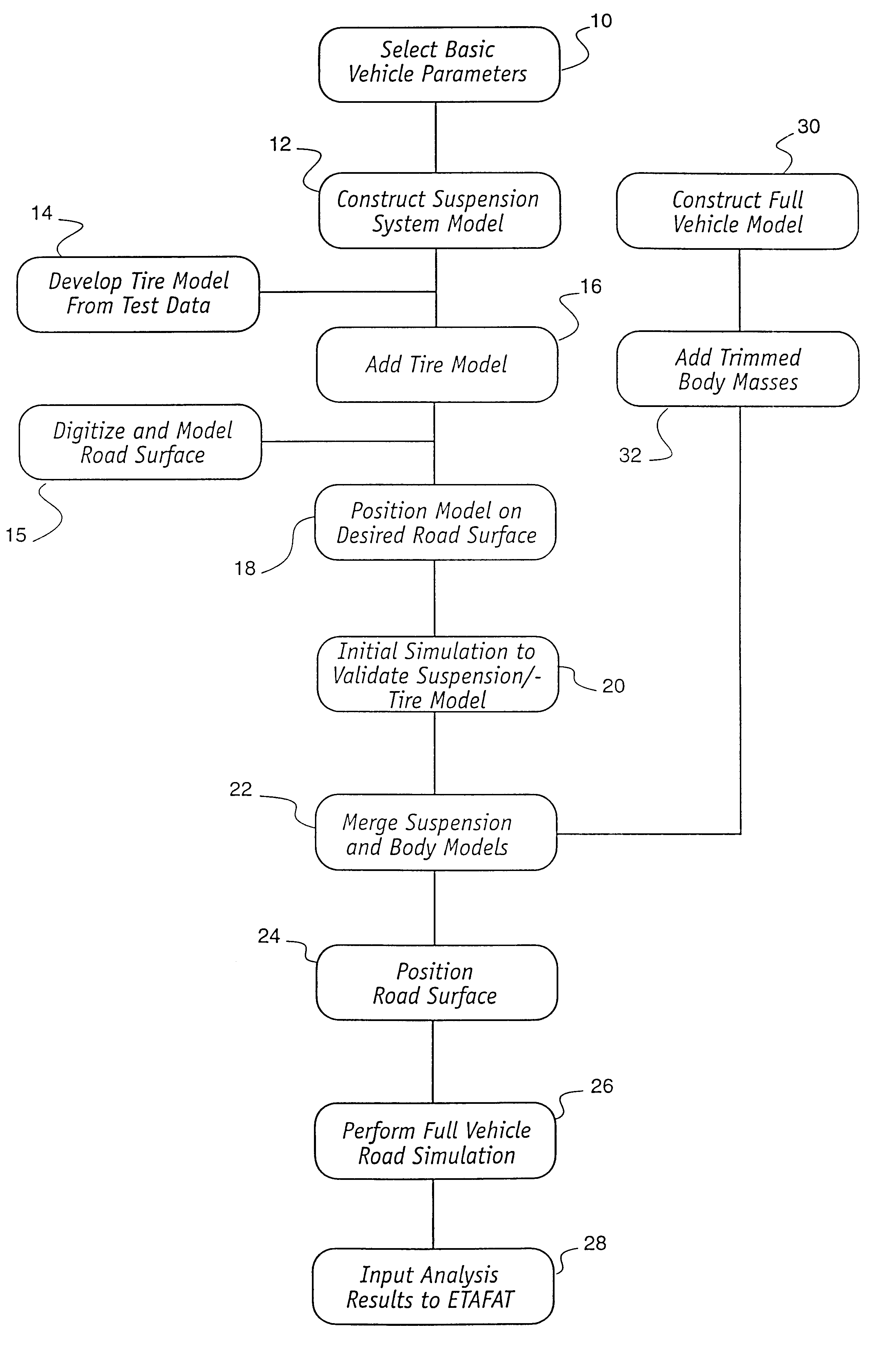
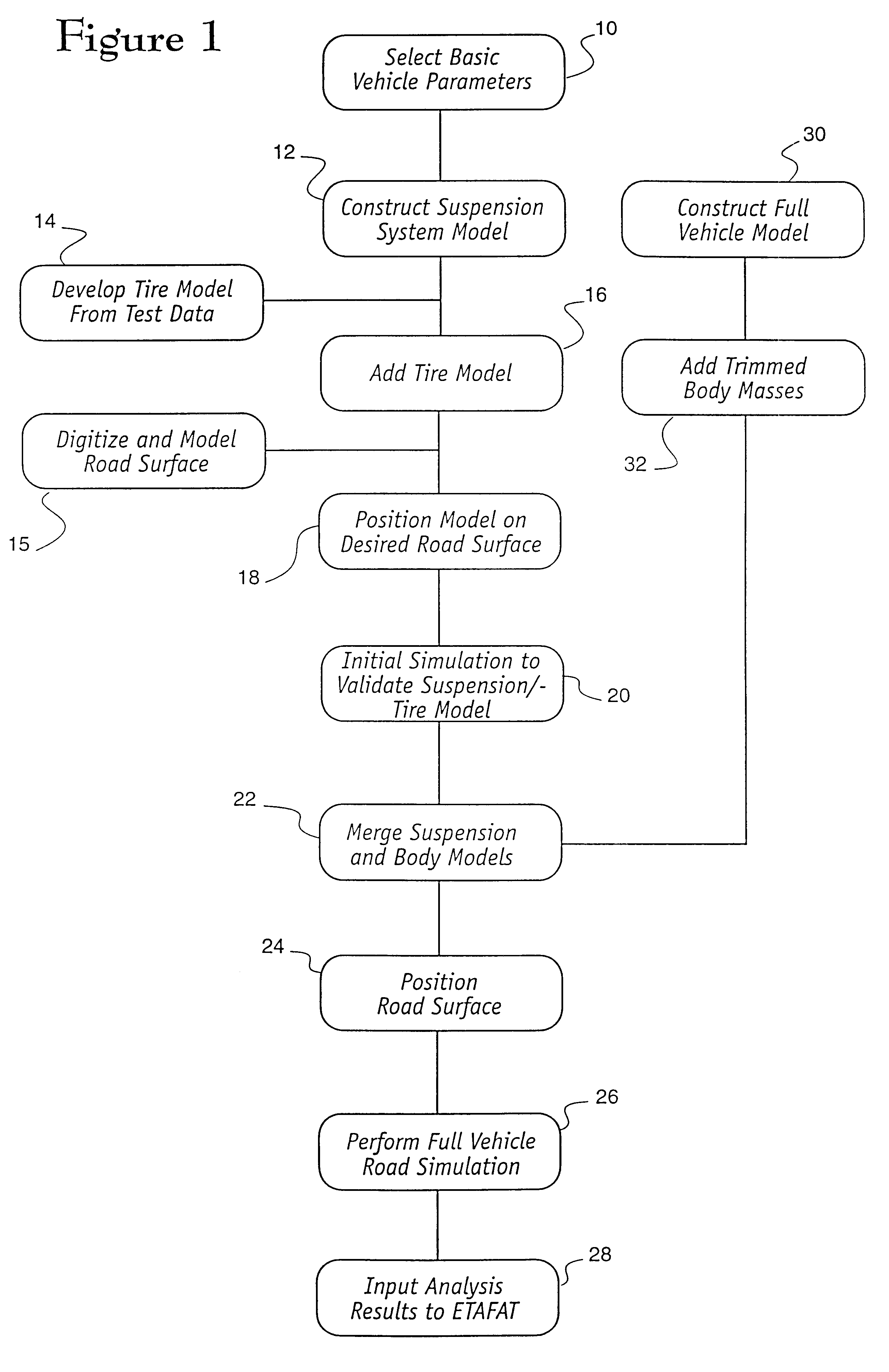
The next step 12 in the inventive method is the creation of a vehicle suspension model utilizing the same techniques above-described. In the invention herein described, the vehicle suspension model is created without concern for the detailed specific physical structure of the vehicle, and instead of the creation of a detailed computer vehicle model, the suspension model is created in relation to a simplified vehicle body and chassis model, which comprises only a single element having a prescribed mass, but no particular physical structure. There are many benefits of this method. By reducing the number of vehicle components which are modelled and simulated, the calculations required during the analysis steps are drastically reduced. A full vehicle model, including tires, wheels, suspension, body, seats, engine, transmission and other components can consume several days of simulation computations. A simple suspension model, without a vehicle body and other vehicle components in detail...

second embodiment

the method of the invention is also diagramed in FIG. 1. In the first embodiment above, a preliminary evaluation of the performance of the vehicle suspension system in relation to the roadway can be obtained, utilizing only the most fundamental information regarding the motor vehicle under test. Utilizing advanced FEA modelling techniques, however, the alternative inventive method herein described contemplates the creation of FEA models of the desired motor vehicle. Construction of this model may include incorporation of vehicle accessories, prescribed vehicle loading, and even the presence of occupants within the vehicle.

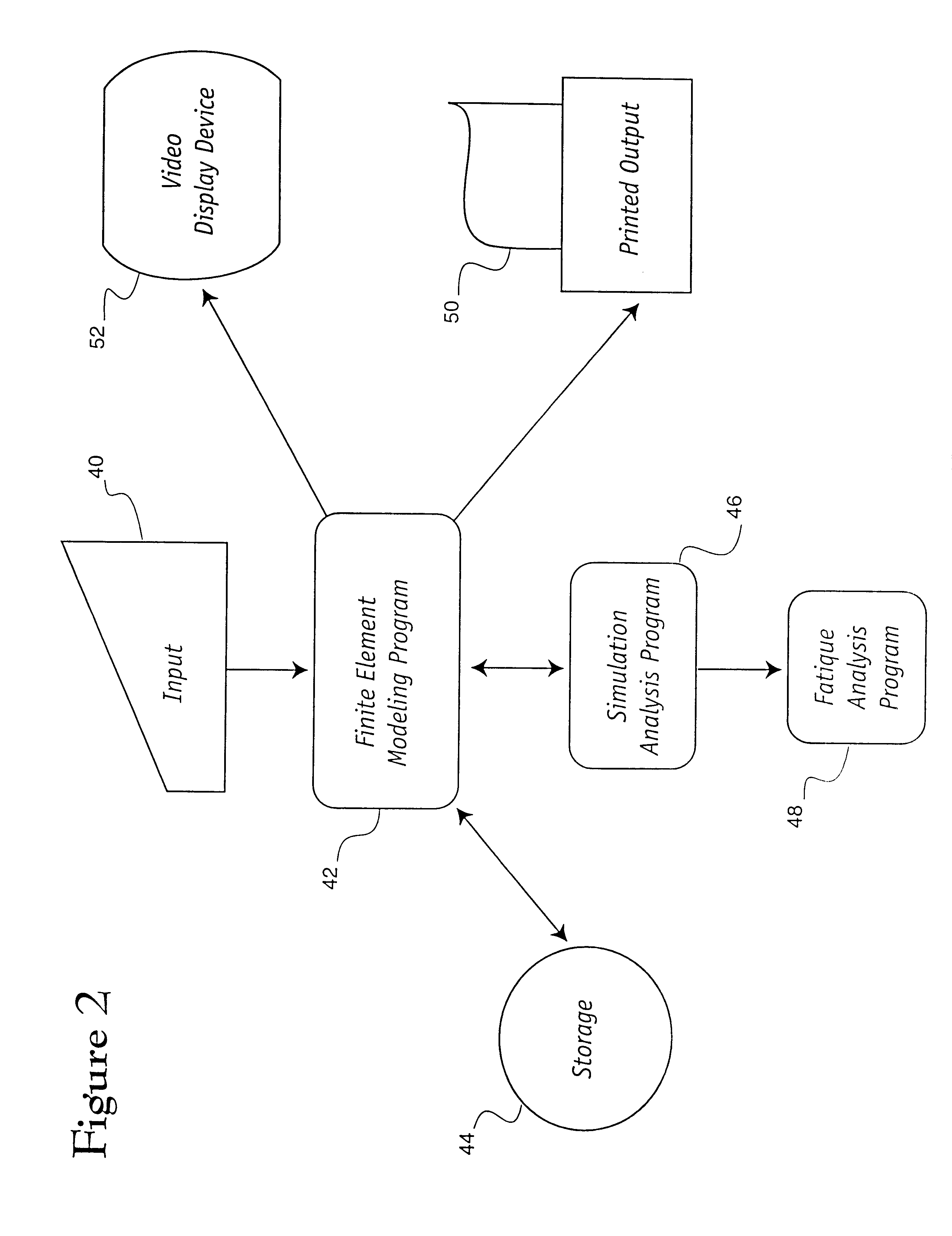
The computer model of the vehicle so created is stored, on an interim basis, in the computer's memory or storage device for subsequent manipulation as herein described. In the second embodiment, however, in addition to the steps above-outlined, a full vehicle model is constructed 30, to include the addition 32 of trimmed body masses in the steps in the inventive me...


PUM


Abstract

The present invention is directed to a system and method for simulating the interaction of a simulated vehicle with one or more simulated road surfaces. A computer modelling program is used to create a computer-based road surface model and a computer-based vehicle model. The computer-based vehicle model may include a body model, a chassis model, a suspension model, a wheel model and a tire model. A computer simulation engine program is operative with the computer-based road surface and vehicle models to selectively simulate the interaction therebetween and provide simulation data relative thereto. The simulation data may be used to identify high stress areas or low durability areas of the vehicle or to compute vehicle suspension parameters.

Description

FIELD OF THE INVENTIONThe invention is an improved system and method for simulating the interaction of a motor vehicle and a road surface, and specifically, pertains to a system and method of using computer models of a vehicle's wheels and tires to evaluate vehicle performance in relation to a computer model of a roadway.BACKGROUNDSystems for the simulation of vehicle operation are well known. Among these systems are vehicle operating simulators, which can be operated by a driver manipulating conventional controls and producing visual, aural and tactile feedback, such as those taught by Briggs, et al, in U.S. Pat. No. 4,952,152 and DeGroat, et al, U.S. Pat. No. 5,277,584.Systems for the analysis of the forces imposed on a motor vehicle during operation are also well known. Using traditional finite element analysis (FEA) techniques, it is possible to construct so-called FEA models of vehicles and their component parts utilizing a computer, and further, to use the computer to simulate...

Claims


Application Information

Patent Timeline
Patent Type & Authority Patents(United States)
IPC IPC(8): G01M17/007
CPCG01M17/007G06F17/5018G06F17/5095B60C99/006B60G2206/99Y02T10/82Y10S188/01G06F30/15G06F30/23
Inventor TANG, YUE-LI A.PALMER, TIMOTHY J.
Owner ENG TECH ASSOC
Why Eureka
Try Eureka