Plate stacker apparatus

Inactive Publication Date: 2001-02-27
GENESEE BIOMEDICAL +2
View PDF9 Cites 42 Cited by
  • Summary
  • Abstract
  • Description
  • Claims
  • Application Information

AI Technical Summary

Problems solved by technology

This is a disadvantage.
This process is inefficient and time-consuming.
Another problem with current stackers is that current stackers are generally fixedly mounted on top of a transfer mechanism.
Thus, it is not possible to load the stack of microwell plates in one area, and then locate that stack onto the transfer mechanism: both the stacker and the transfer mechanism must be manipulated together.
Another problem with the current stack

Method used


Image

  • Plate stacker apparatus
  • Plate stacker apparatus
  • Plate stacker apparatus

Examples


Embodiment Construction

Illustrative embodiments will now be described with reference to the accompanying figures.

The invention relates to an apparatus and a method to increase the throughput of manipulating microwell plates when performing various protocols. The invention increases throughput while remaining compact in size. Further aspects and advantages of the invention will become apparent from consideration of the following description and drawings.

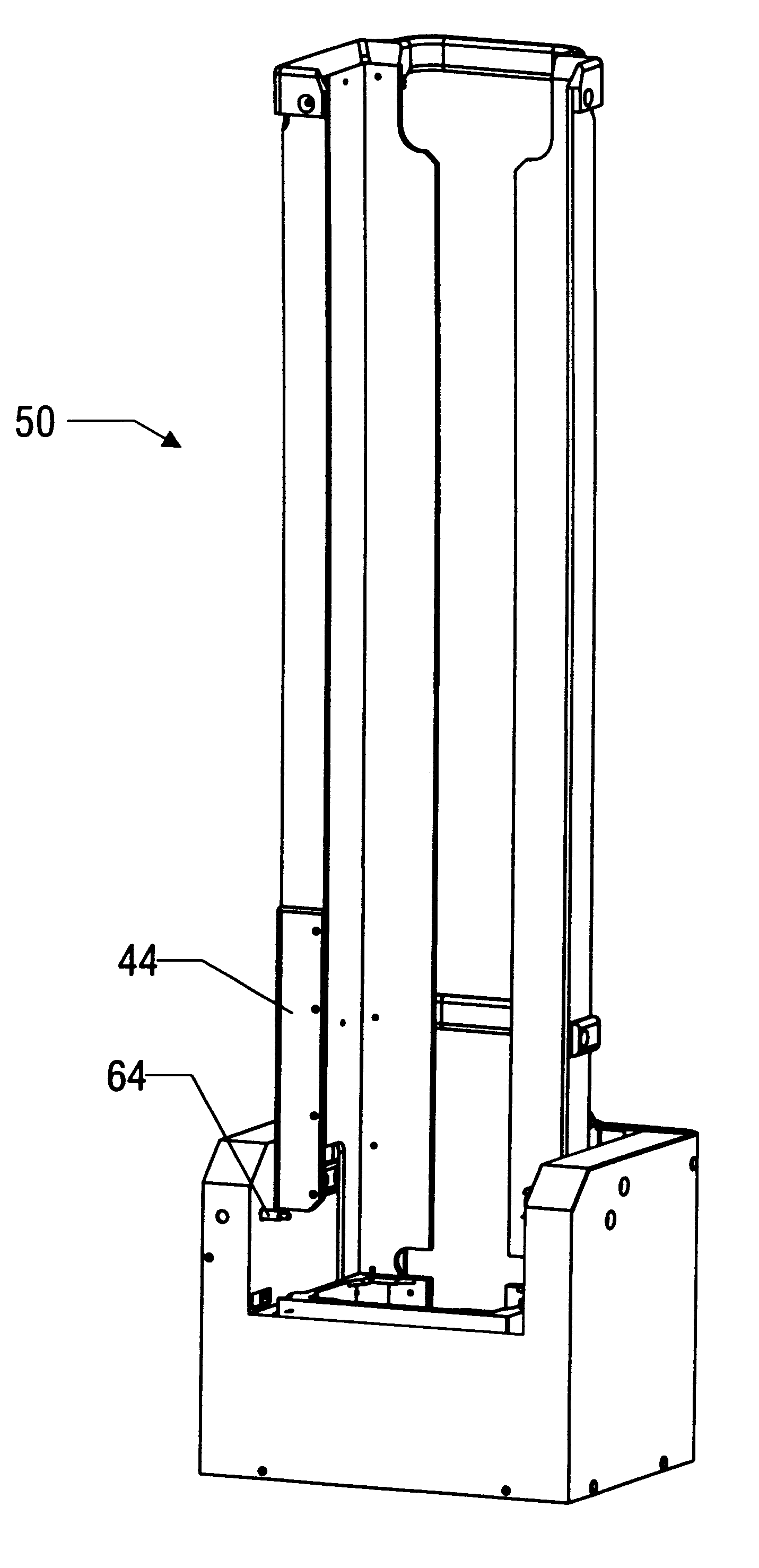
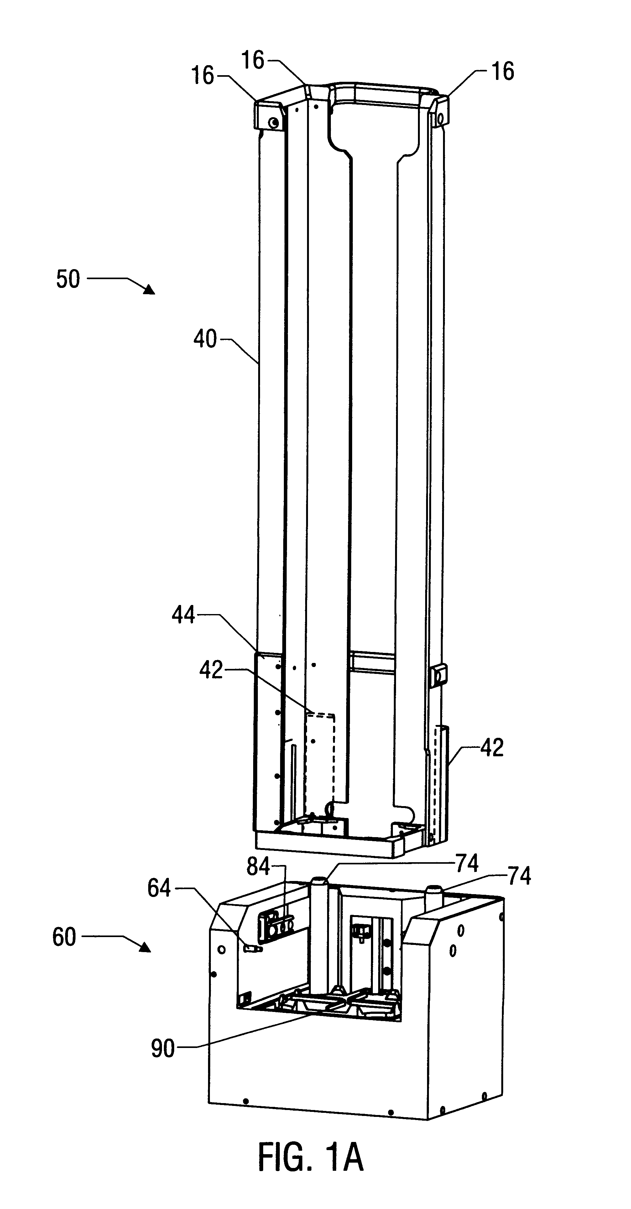
FIG. 1A shows two embodiments of the invention: rack 40 and stacker 50. Rack 40 has three vertical corner sections 16. Door 44 is located on one end of one vertical corner section 16--the end closest to the stacker base 60. Door 44 is operably attached to corner section 16 and is capable of opening by sliding up corner section 16. In this way, when rack 40 is loaded with microwell plates, the microwell plates are may be removed when door 44 is open. When door 44 is closed, i.e. when rack 40 is removed from base 60, door 44 is closed. This prevents microwell...


PUM


Abstract

A plate stacker is described for use in the field of sample analysis. The plate stacker increases the rate and ease with which sample carriers such as microwell plates may be interfaced with an automated system and includes a removable rack attached to a base to allow plates to be transported to and from an automated system. The stacker rack includes a door which allows for a compact stacker thus allowing manipulation of the microwell plates in a compact area. Generally, the plate stacker provides a means to allow a user to interface with an automated system. The rack portion of the stacker allows the user to load and unload microwell plates into the system in batches by loading or unloading multiple individual plates into or out of the rack. The base portion allows the automated system to load and unload individual microwell plates from the stacker.

Description

1. Field of the InventionThe invention relates to the field of sample analysis. More particularly, this invention relates to an apparatus and method for increasing the rate at which microwell plates can be manipulated in performing various experiments.2. Description of the Related ArtIn the field of molecular biology, the process of sequencing nucleic acids has become significant as more and more diseases are linked to genetic abnormalities. The process of identifying genes and their corresponding proteins for potential therapeutic applications is well known.Other types of molecular biology procedures are also important for therapeutic and research purposes including DNA restriction mapping, DNA probe generation, replication, DNA sample processing, and cycle sequencing. Generally, these procedures involve a substantial number of steps including, without limitation, automated liquid handling, robotic movement of the samples, pipetting of small amounts of many different reagents into ...

Claims


Application Information

Patent Timeline
IPC IPC(8): G01N35/02G07F11/16G01N35/04
CPCG01N35/028G07F11/16G01N2035/0425
Inventor BEVIRT, JOEBENBRINTON, GABRIEL NOAH
Owner GENESEE BIOMEDICAL
Why Eureka
Try Eureka