Apparatus and method for fusion joining a pipe and fittings

a technology of fusion and fittings, applied in the direction of hose connection, electric/magnetic/electromagnetic heating, mechanical apparatus, etc., can solve the problems of affecting the quality of fusion

Inactive Publication Date: 2001-02-27
UPONOR LTD
View PDF13 Cites 33 Cited by
  • Summary
  • Abstract
  • Description
  • Claims
  • Application Information

AI Technical Summary

Benefits of technology

It is another object of this invention to provide a novel induction heating element which can be quickly and easily field-installed within a conventional thermoplastic fitting or within an electrofusion fitting from which the moulded-in heating element has been omitted.
According to the invention, it is not necessary to use a conventional heat fusion fitting that has an insert-moulded heating element. In the apparatus and method of this invention, the fitting does not require a two-step method for manufacturing the fitting and the electrofusion method of this invention can be accomplished with standard, off-the-shelf thermoplastic fittings or with electrofusion fittings from which the moulded-in electrofusion element has been omitted. Because of the simplified manufacturing process associated with standard, off-the-shelf thermoplastic fittings, it is possible to reduce overall manufacturing costs while increasing the availability of differently sized fittings which can be used with the induction fusion method for joining a pipe with respect to a fitting.
In a particularly preferred embodiment of the invention, the induction heating element is wholly inserted within the socket or mounted on the flange and preferably is provided with regions of plastics material that are substantially unheated and form "cold zones" which help to contain the melt during the fusion step. Melt containment helps to build up pressure in the melt region and improves the quality of the fusion joint. The regions of plastics material forming the "cold zones" are preferably continuous and uninterrupted, that is to say, they do not have wires or conductors passing through them. The regions of plastics material can be provided as separate components, but preferably they are moulded with the plastics material encasing or wholly surrounding the induction heating element.

Problems solved by technology

The proposed design complicates manufacture and it is difficult to connectorise the coil to an external power source.
In addition, the existing wires provide potential leak paths from the joint region.
Thus, such methods cannot be used with existing conventional plastics fittings that do not contain a moulded-in heating element.
The electrofusion heat generating unit of GB2272663 is inconvenient, due to the necessity of providing a large flange to accommodate the terminals of the coil, difficult to overmould and expensive to manufacture.
The bare induction fusion element, even when pressure inserted into the socket, is not completely surrounded by plastics material and is liable to overheat and be subject to thermal runaway.
The overheated region of the element can also cause local degradation of the thermoplastic material.
In such cases usually the melt region cannot be contained, and thus a good fusion joint cannot be made.

Method used


Image

  • Apparatus and method for fusion joining a pipe and fittings
  • Apparatus and method for fusion joining a pipe and fittings
  • Apparatus and method for fusion joining a pipe and fittings

Examples


Embodiment Construction

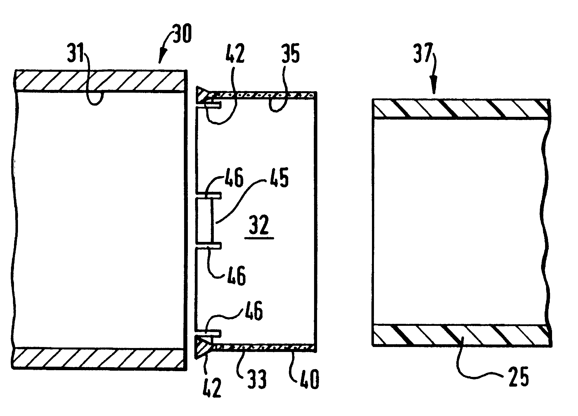
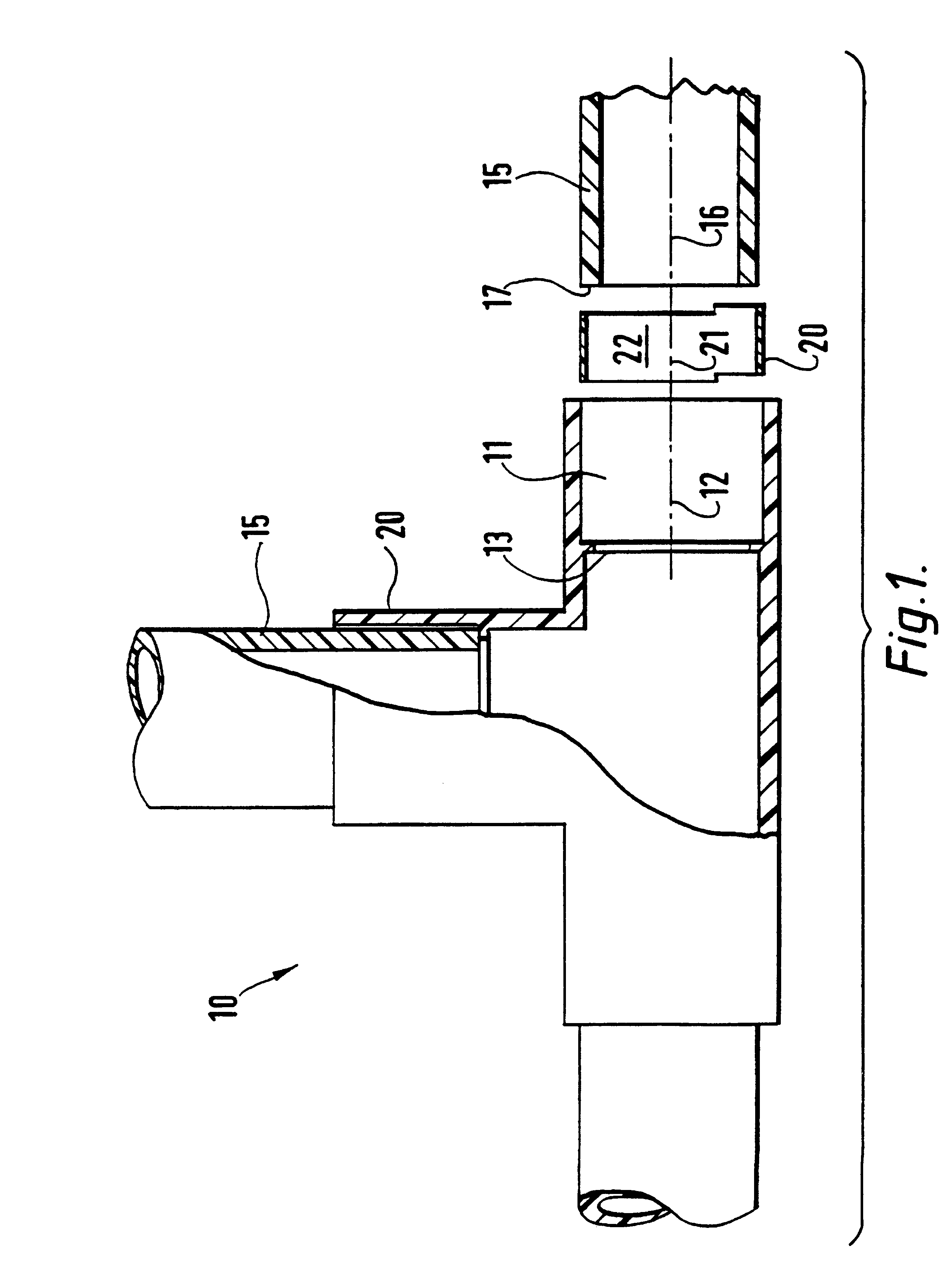
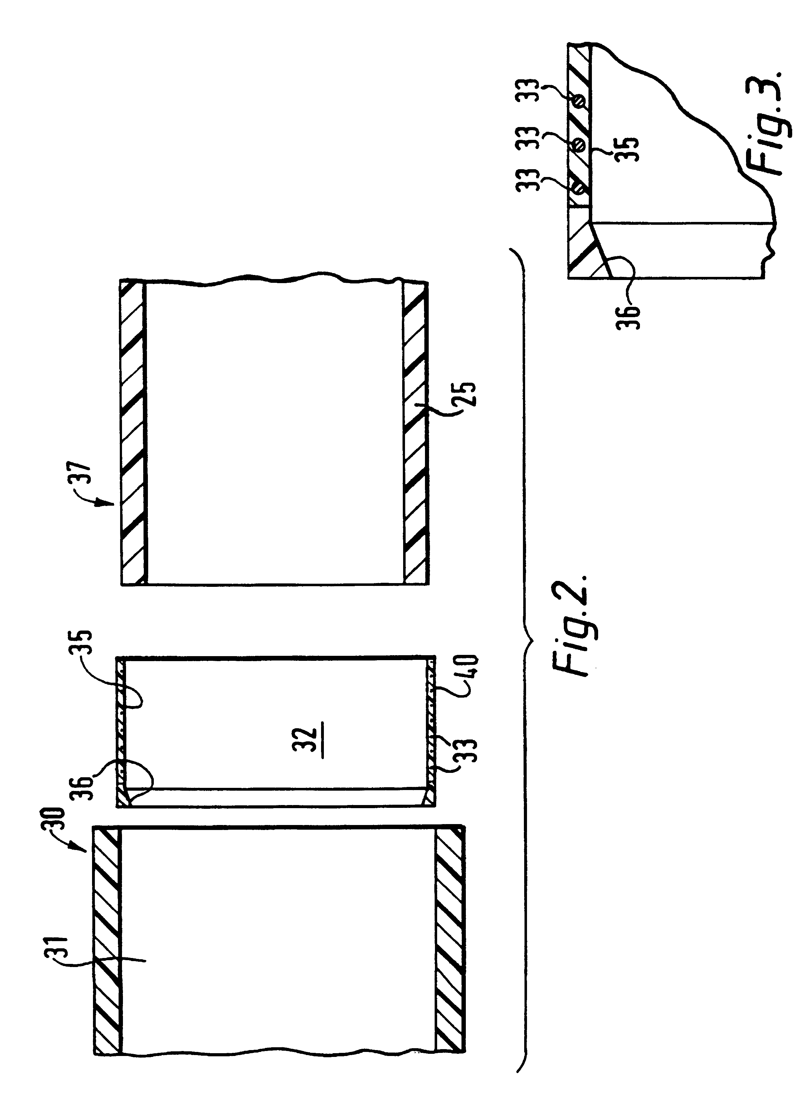
The apparatus and method according to this invention can be used to fusion join standard, off-the-shelf thermoplastic fittings either directly to or with respect to a pipe. Referring to FIG. 1, fitting 10 is shown as a standard tee. As shown in FIG. 2, fitting 30 is a standard polyethylene pipe. It is apparent that any suitable fitting known to those skilled in the art, which in this case has a socket end, can be used as fitting 10, according to preferred embodiments of this invention. As used throughout this specification and in the claims the word fitting is intended to relate to any coupling member or other suitable fitting that forms a socket or a flange for joining with a pipe or similar member.

The vertically oriented pipe 15, as shown in FIG. 1, is mounted within socket 11 of fitting 10. In such mounted position, induction heating sleeve element 20 is sandwiched between pipe 15 and fitting 10.

The exploded view portion of FIG. 1, in the horizontally oriented direction on the ri...


PUM

PropertyMeasurementUnit
conductiveaaaaaaaaaa
non-conductingaaaaaaaaaa
thermoplasticaaaaaaaaaa

Abstract

An apparatus for fusing a pipe to a fitting includes an induction heating element wholly encased or coated with a flusible thermoplastic polymeric material, a fitting having a socket or a flange. The induction heating element is adapted to be inserted into said socket or mounted on said flange, the fitting and the element together defining a throughbore, a portion of a pipe adapted to be inserted into the throughbore or mountable on said flange. The apparatus also includes a locating and maintaining member on the induction heating element with one or more projections adapted to be snap-fitted on the fitting, the pipe or both, and capable of locating and maintaining the position of the heating element relative to the fitting or the member portion. The induction fusion element is capable of fusing the fitting and the pipe portion.

Description

1. Field of the InventionThis invention relates to an apparatus and method for fusion joining a pipe with respect to a fitting, and more particularly to an improved apparatus and method wherein a novel heating element is insertably positioned between a fitting and a portion of the pipe.2. Description of Prior ArtVarious conventional apparatus and methods exist for fusion joining polyethylene pipes, such as those that employ heat fusion, electrofusion or induction fusion techniques. Electrofusion uses a conventional resistive heating method wherein a wire spiral coil is typically internally moulded within the thermoplastic fitting. An electrical current is applied directly to the wire coil via terminals on the fitting which results in the coil heating the thermoplastic material to a temperature which softens the thermoplastic material enough to fuse the pipe to the fitting.In GB1149716 there is described an electrical resistance heating coil for use as a welding sleeve for joining pl...

Claims


Application Information

Patent Timeline
Patent Type & Authority Patents(United States)
IPC IPC(8): B29C65/36B29C65/34F16L47/02
CPCB29C65/362B29C66/80B29C66/52297F16L47/02B29C65/34B29C66/112B29C66/52241B29C66/1224B29C66/131B29C66/1222B29C66/5221B29C65/3644B29C66/52298B29C65/3612B29C66/52292B29C65/3468B29C65/368Y10S285/921B29C65/3668B29C65/3476B29C65/364
Inventor SMITH, CIN LEE
Owner UPONOR LTD
Why Eureka
Try Eureka