Electrophotographic printer

Inactive Publication Date: 2001-02-27
OKI DATA CORP
View PDF2 Cites 0 Cited by
  • Summary
  • Abstract
  • Description
  • Claims
  • Application Information

AI Technical Summary

Benefits of technology

Another object of the invention is to provide an electrophotographic printer where energization of the lightemitting elements is started at shifted timings so that a total current required for driving the light-emitting elements is as small as possible.

Problems solved by technology

The dither reduces the resolution of the image.
The error diffusion method suffers from an inherent problem of a striped pattern.
Thus, these methods impose limitations on high quality print out.
Electrophotographic printers using conventional LED heads suffer from a problem that simultaneously energizing all the LEDs requires a large current that causes noise.
The noise in turn causes deteriorated print quality.

Method used


Image

  • Electrophotographic printer
  • Electrophotographic printer
  • Electrophotographic printer

Examples


first embodiment

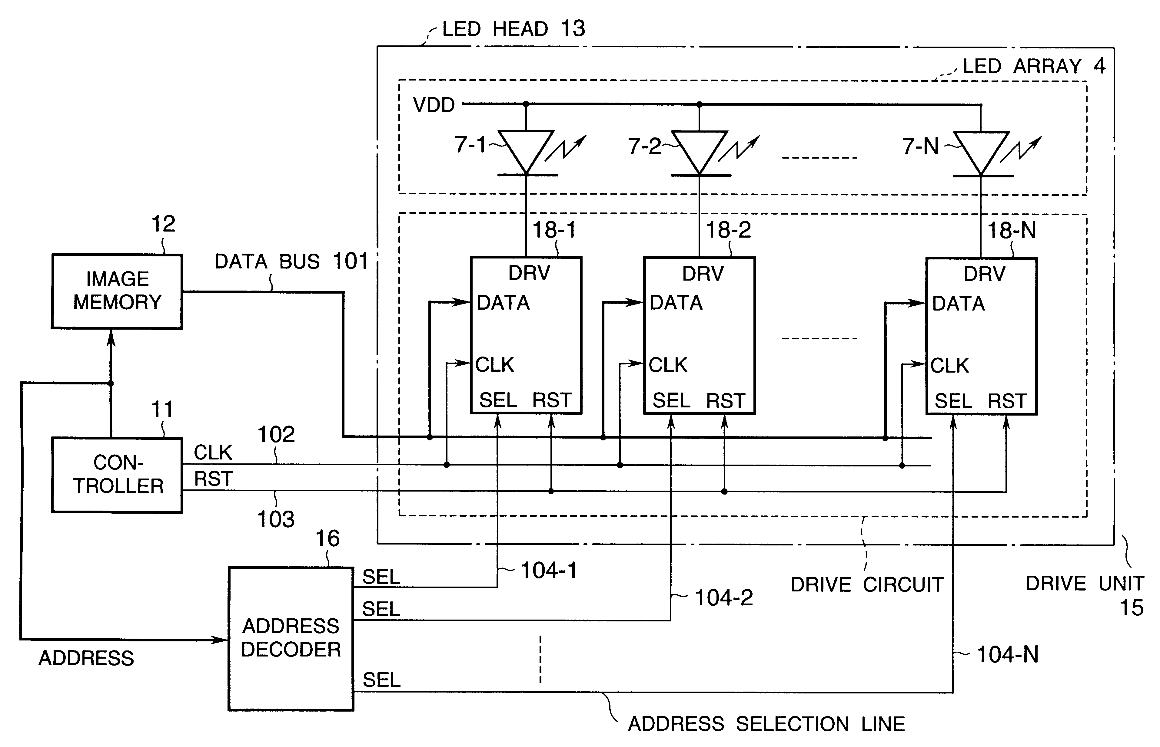
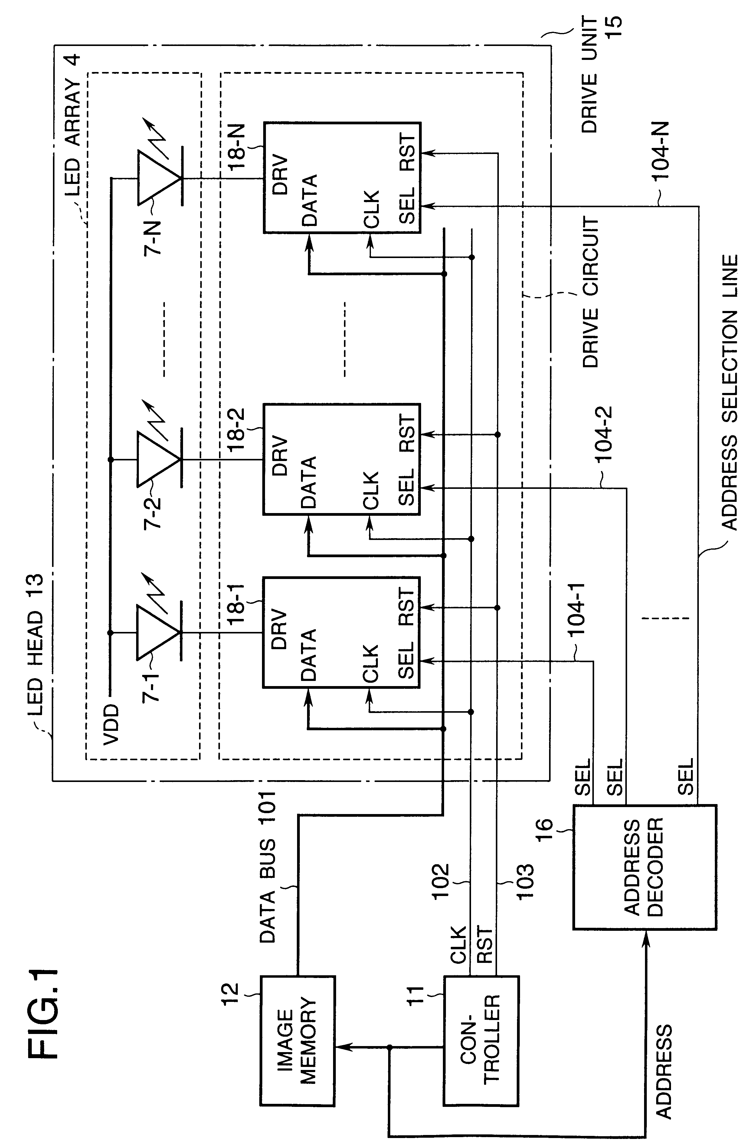
FIG. 1 shows a relevant portion of a first embodiment of an electrophotographic printer of the invention. The electrophotographic printer includes a controller 11, an image memory 12, an LED head 13, and an address decoder 16. The LED head 13 includes an LED array 4 having LEDs 7-1 to 7-N aligned in line, and a drive unit 15 having drive circuits 18-1 to 18-N. The drive circuits are connected to corresponding LEDs.

Each of the drive circuits 18 has input terminals DATA, CLK, SEL, and RST and an output terminal DRV. The input terminals DATA are connected to the image memory 12 via a data bus 101 that includes a plurality of data signal lines. The input terminals CLK are connected to the controller 11 via a common control signal line 102. The input terminals SEL are connected to the address decoder 16 via the address selection lines 104-1 to 104-N. The input terminals RST are connected to the controller 11. The output terminals DRV are connected to corresponding LEDs 7.

The image memory...

second embodiment

FIG. 5 shows a relevant portion of a second embodiment of an electrophotographic printer of the invention. The electrophotographic printer includes a controller 21, an image memory 12, and an LED head 23. The LED head 23 includes an LED array 4 having LEDs 7-1 to 7-N arranged in line, and a drive unit 25 that drives the LEDs 7-1 to 7-N. The drive unit 25 has drive circuits 28-1 to 28-N that are connected to corresponding LEDs 7. The drive circuits 28 hold addresses representing corresponding LEDs.

Each of the drive circuits 28-1 to 28-N has an output terminal DRV and input terminals DATA, ADR, and RST. The input terminals DATA are connected to the image memory 12 via the data bus 101 that includes a plurality of data signal lines. The input terminals CLK are connected to the controller 21 via the common control signal line 102. The input terminals RST are connected to the controller 21 via the control signal line 103. The input terminals ADR are connected to the controller 21 via add...

third embodiment

The third embodiment simplifies the complexity of the wiring between the controller 31 and drive circuits 38 and interconnection between the drive circuits in the drive unit 35, allowing miniaturizing of the circuit. The controller 31 is required only to output the LT on a line-by-line basis, so that the controller 31 controls the drive circuits in a simple way.


PUM


Abstract

An electrophotographic printer has a print head that illuminates a photoconductor to form an electrostatic latent image. The print head has light-emitting elements. Each corresponding to a pixel of the image and emitting light when driven. Drive circuits are provided for driving the light-emitting elements. Each drive circuit drives a corresponding one of the light-emitting elements in accordance with a value of the pixel. A controller controls the drive circuits to start driving corresponding light-emitting elements in a predetermined order.

Description

The present invention relates to an electrophotographic printer where a surface of a photoconductor is illuminated by a fixed print head having a plurality of light-emitting elements.DESCRIPTION OF THE RELATED ARTAn electrophotographic printer is a known conventional apparatus where a surface of a photoconductor is illuminated by a non-movable print head having a plurality of light-emitting elements. Such types of print head include an LED head and LCS (liquid crystal shutter) head. The print head has non-movable part as the name implies and a short light path, simplifying its optical system as well as lending itself to miniaturizing the print head.FIG. 13 illustrates a part of a conventional printer. An LED head 3 is constructed of an LED array 4, drive unit 5, and optical system, not shown. The LED array 4 has a plurality of LEDs 7. The drive unit 5 has a plurality of drive circuits 8 each of which drives a corresponding LED 7. The optical system directs the light emitted from the...

Claims


Application Information

Patent Timeline
IPC IPC(8): G06K15/12B41J2/45B41J2/44B41J2/455
CPCG06K15/1247
Inventor WAKASUGI, NOBUO
Owner OKI DATA CORP
Why Eureka
Try Eureka