Zoom lens device with zooming position detector

a detector and zooming technology, applied in the field of zoom lens devices, can solve the problem of inevitably enlarge the whole size of the camera

Inactive Publication Date: 2001-02-27
FUJIFILM CORP
View PDF11 Cites 39 Cited by
  • Summary
  • Abstract
  • Description
  • Claims
  • Application Information

AI Technical Summary

Benefits of technology

Another object of the present invention is to provide a light-shielding device for preventing extraneous light entering inside a lens device through a clearance between a front cover member of the lens device and a member that is placed behind the front cover member and rotates relative to the front cover member.
To achieve the second object, a lens device according to the present invention is comprised of a lens barrel, an internal member that is mounted inside the lens barrel and rotatable about an optical axis of the zoom lens device relative to the lens barrel but immovable in a direction of the optical axis relative to the lens barrel, and a front cover member secured to a front end of the lens barrel, the front cover member having an opening for exposing a center portion of the internal member, wherein a front face of the internal member and a rear surface of the front cover member are engaged with each other through a labyrinth engagement, and a clearance is provided in between the internal member and the front cover member for allowing the internal member to rotate relative to the front cover member.

Problems solved by technology

However, the light-shielding ring is not preferable for a lens device where a front lens frame is rotatably held in a barrel, and a front cover member having an opening for exposing the front lens is attached to a front end of the barrel, and a clearance is provided between the front lens frame and the front cover member for allowing the front lens frame to rotate relative to the front cover member.
Either of the prior zooming position detectors needs a mounting space outside the movable lens barrel, which inevitably enlarges the whole size of the camera.

Method used


Image

  • Zoom lens device with zooming position detector
  • Zoom lens device with zooming position detector
  • Zoom lens device with zooming position detector

Examples


Embodiment Construction

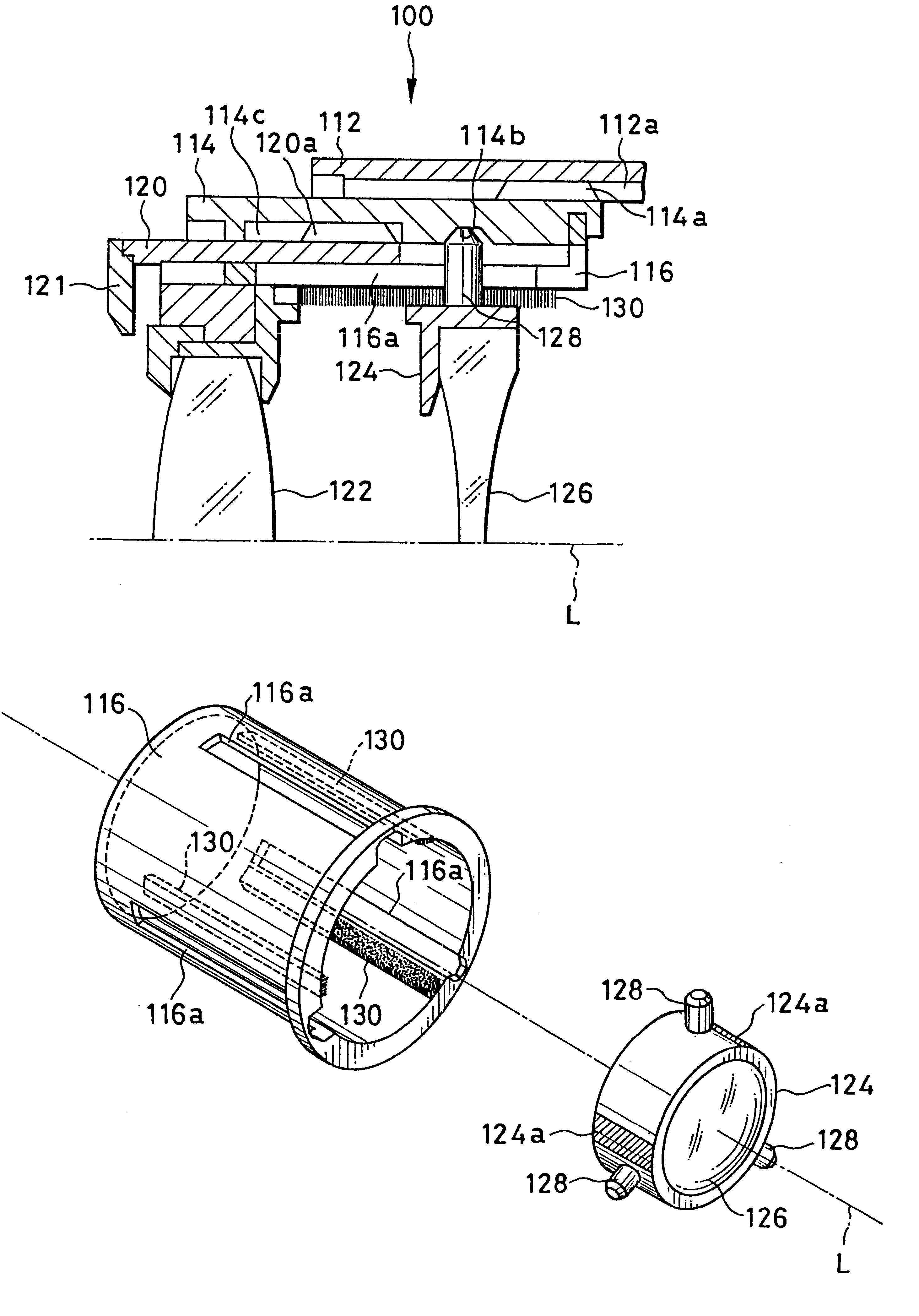
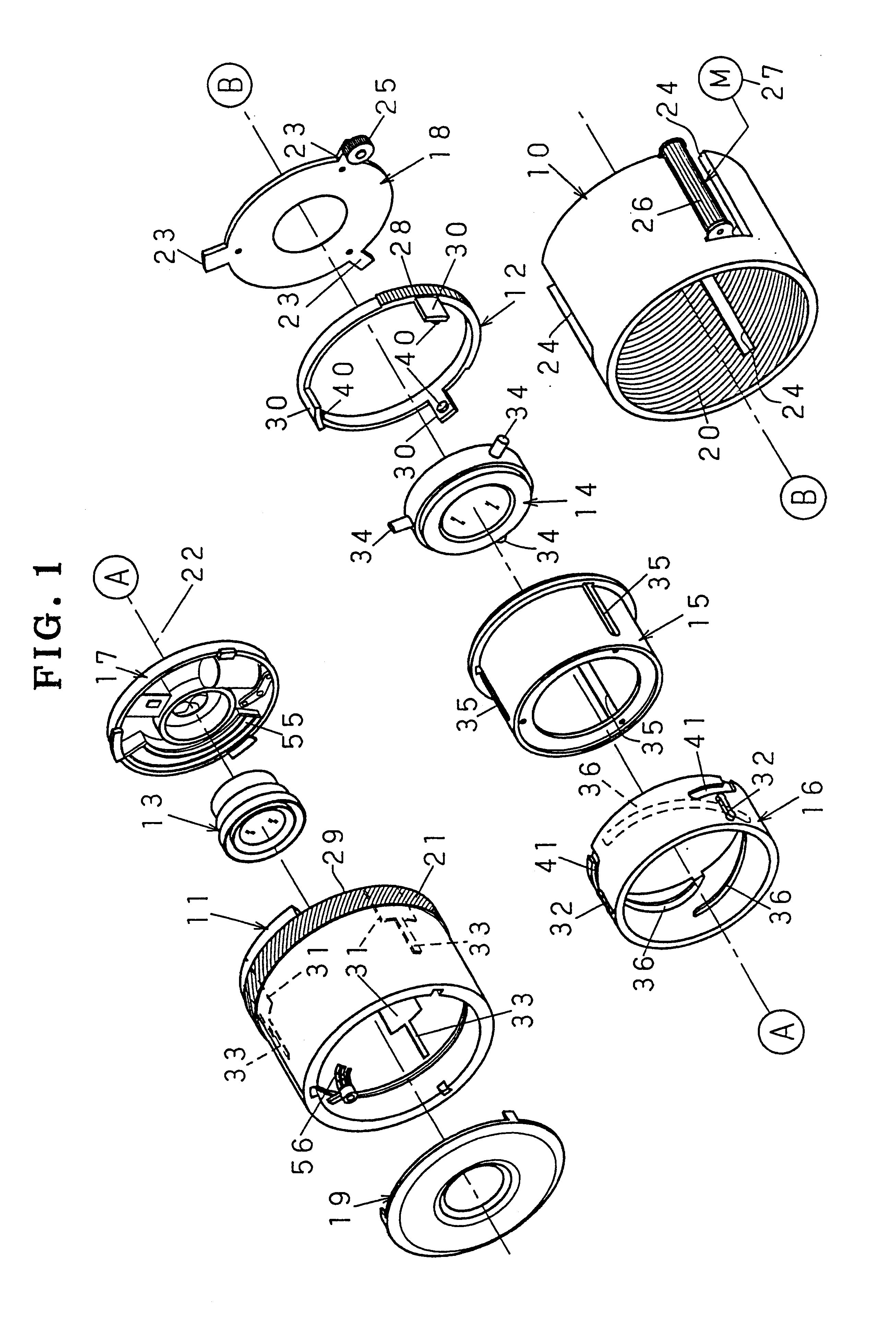
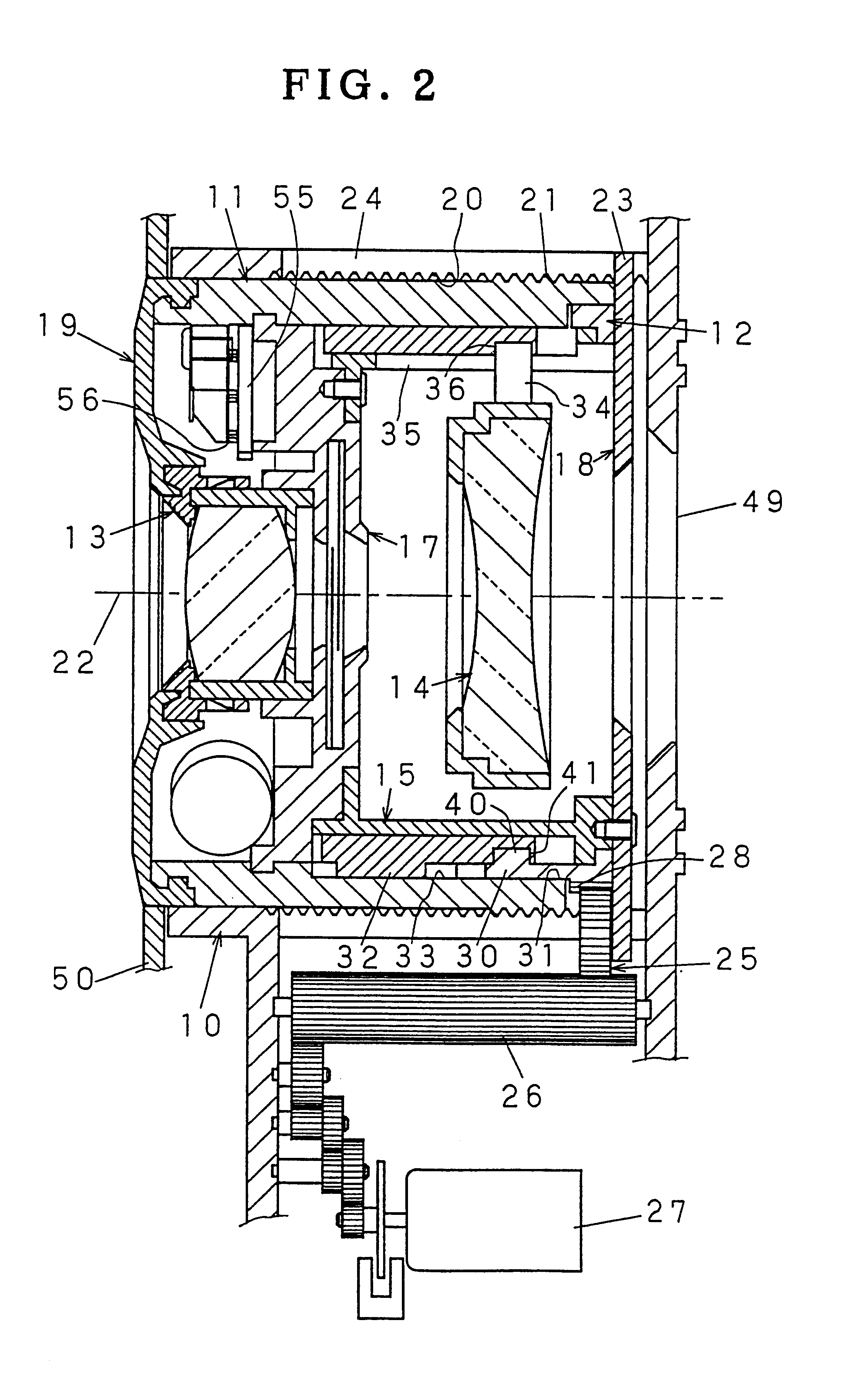
As shown in FIGS. 1 and 2, a zoom lens device according to a first embodiment is applied to a two component mechanical compensation type zoom lens system consisting of two lens groups. The zoom lens device is mainly constituted of a fixed barrel 10, a helical movement barrel 11, a drive ring 12, a front lens frame 13 holding a front lens group, a rear lens frame 14 holding a rear lens group, an axial movement barrel 15, a cam barrel 16, a shutter unit 17, an axial movement guide ring 18 and a decorative cover plate 19.

The fixed barrel 10 has an internal or female helicoid 20 around its inner periphery. The helical movement barrel 11 has an external or male helicoid 21 around its outer periphery, which is engaged with the internal helicoid 20 of the fixed barrel 10. Thereby the helical movement barrel 11 can rotate inside the fixed barrel 10 about an optical axis 22 of the lens system while moving in the axial direction according to the lead of the helicoids 20 and 21. The decorative...


PUM


Abstract

A zoom lens device has a zooming position detector consisting of a code plate and a brush device. The code plate is mounted to a front face of a shutter unit that is attached to a front end of an axial movement barrel. The axial movement barrel is located inside a helical movement barrel so as to be immovable in the axial direction relative to the helical movement barrel, but is rotated relative to the helical movement barrel for zooming. The brush device is mounted to an inner peripheral portion of a lens barrel that is located near the face of the shutter unit and rotates relative to the face of the shutter unit, such that the electric contact strips brush the code plate while the shutter unit rotates relative to the lens barrel for zooming. A zooming position of the zoom lens device is determined based on output signals from the brush device.

Description

BACKGROUND OF THE INVENTION1. Field of the InventionThe present invention relates to a zoom lens device whose lens barrel elements rotate relative to each other for changing the focal length, i.e. for zooming. The present invention relates more particularly to a zoom lens device having a zooming position detector mounted in a compact fashion.2. Background ArtsA zoom lens device has at least front and rear lens groups whose positions are changed relative to a film surface and relative to each other in the direction of the optical axis of the zoom lens device. Since there is a clearance between barrels that hold the front and rear lens groups respectively, extraneous light would enter inside the zoom lens device through the clearance without any light-shielding device. JPY 5-31634 discloses a light-shielding device for a zoom lens device, which is constituted of a light-shielding ring having a resilient lip around its inner rim. The light-shielding ring is placed behind a face flange ...

Claims


Application Information

Patent Timeline
Patent Type & Authority Patents(United States)
IPC IPC(8): G02B15/14G02B7/10
CPCG02B7/10G02B15/14G02B15/142G02B7/102G02B13/009H04N23/50H04N23/69
Inventor IWASAKI, HIROYUKI
Owner FUJIFILM CORP
Why Eureka
Try Eureka