Distributed network computing system for data exchange/conversion between terminals

a network computing and data exchange technology, applied in the direction of instruments, digital transmission, secret communication, etc., can solve the problems of cumbersome processing, physical length of the cable reaches the limit, and it is difficult to uniformly provide an application service to various terminals in such an environment, so as to improve the security function of the terminal and improve the security function.

Inactive Publication Date: 2001-02-27
KK TOSHIBA
View PDF6 Cites 141 Cited by
  • Summary
  • Abstract
  • Description
  • Claims
  • Application Information

AI Technical Summary

Benefits of technology

With this processing, even in a system having various communication infrastructures, the relative difference in data transmission rate/volume/quality among the communication infrastructures can be absorbed. The terminal can receive the same service as that for the remaining terminals although the data format is different. Further, the terminal can be improved in its security function

Problems solved by technology

Therefore, it is very difficult to uniformly provide an application service to various terminals in such an environment.
To provide a service while adjusting the difference in processing capability among the terminals or the difference in communication capability among the communication infrastructures, cumbersome processing must be performed.
However, as the network expands and the number of connected devices increases, the physical length of the cable reaches the limit.
Conventionally, however, no system has been proposed yet to provide the service while adjusting the difference in processing capability among the terminals or the difference in communication capability among the communication infrastructures on a network

Method used


Image

  • Distributed network computing system for data exchange/conversion between terminals
  • Distributed network computing system for data exchange/conversion between terminals
  • Distributed network computing system for data exchange/conversion between terminals

Examples


second embodiment

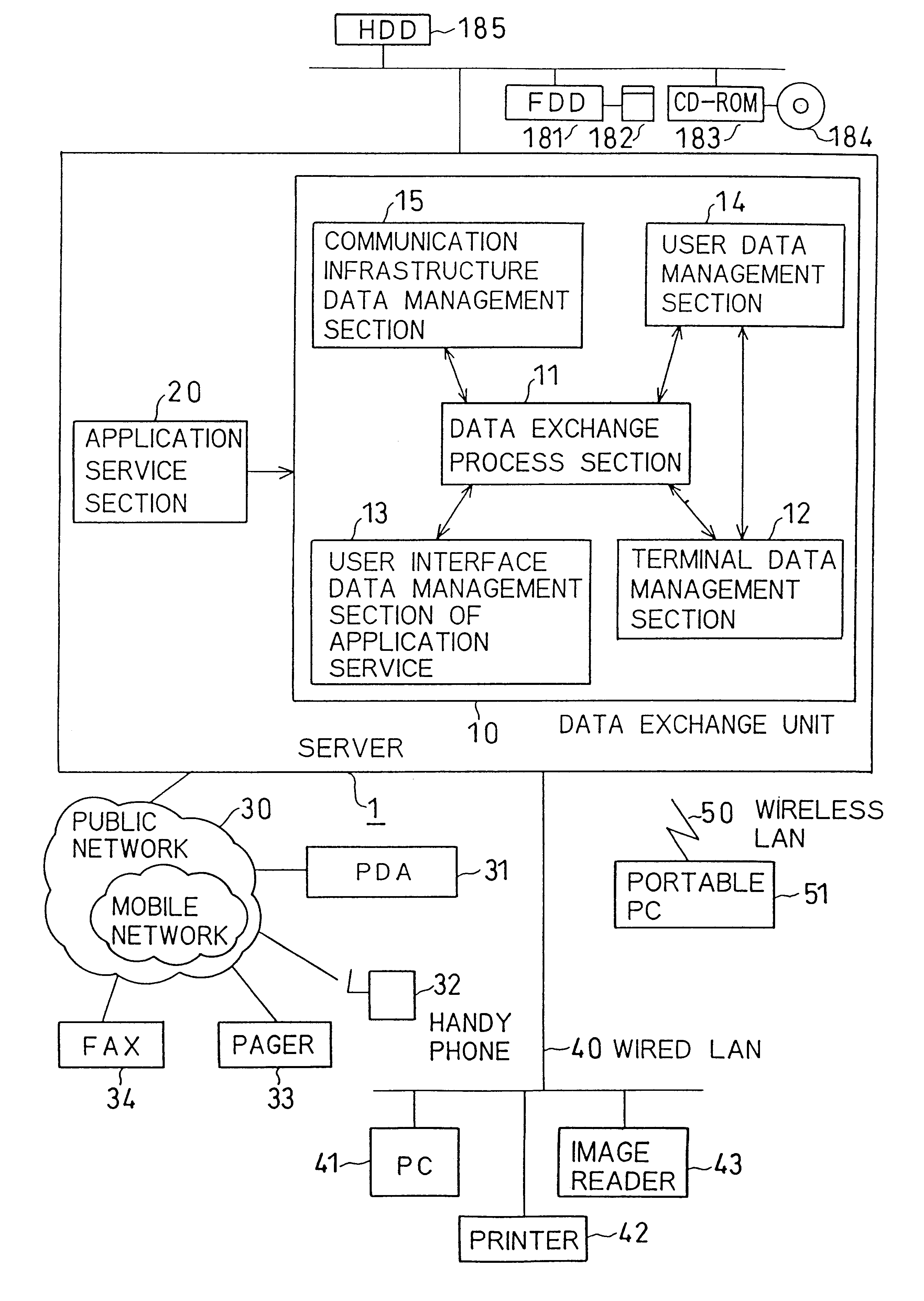
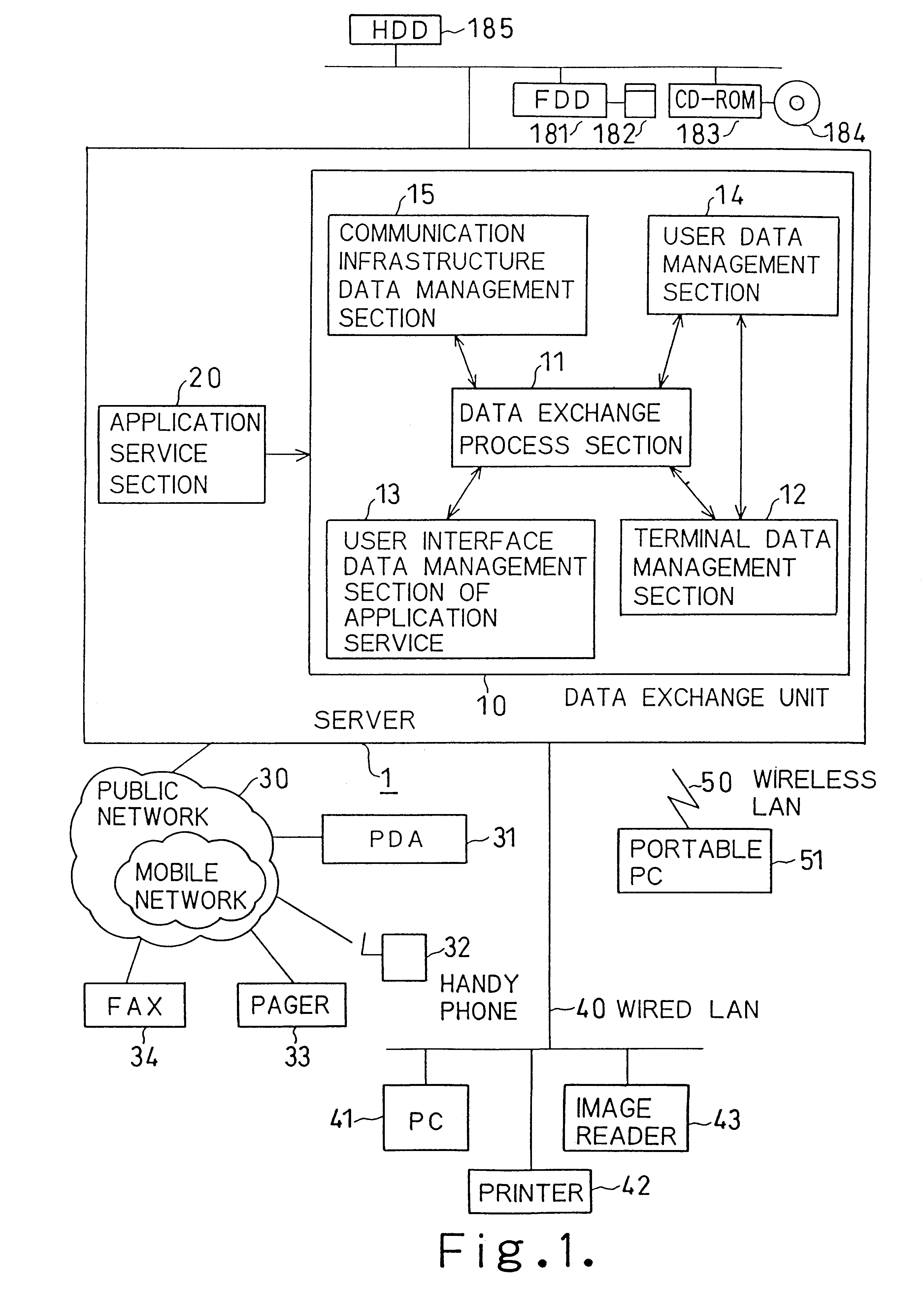
FIG. 39 is a block diagram showing the structure of a distributed network computing system according to the present invention. The same reference numerals as in FIG. 1 denote the same parts in FIG. 15, and a detailed description thereof will be omitted. FIG. 39 is different from FIG. 1 in that a plurality of servers 1a to 1e exist on a network. In this embodiment, the servers 1a to 1e are connected to each other via a wired LAN 2 in an office.

The server 1a is a main server computer for providing a service and has an application service section 20. The server 1 has a data exchange process section 11 and operates as a data exchange control server for controlling the entire data exchange process.

The servers 1b to 1e are sub-server computers. The server 1b has a terminal data management section 12 for managing terminal attribute data and operates as a terminal data management server under the control of the server 1a. The server 1c has a user interface data management section 13 for man...

first embodiment

The data exchange process corresponding to the terminal attribute has been described above. When the data exchange process is to be performed in correspondence with the attribute of a communication infrastructure, the servers 1b to 1e are accessed to check the server having the communication infrastructure data management function. The server 1a obtains the communication infrastructure data corresponding to the terminal as the communication partner from the communication infrastructure data management section 15 in the server 1e, thereby executing the service providing process by the data exchange process as described in the In this case, the data exchange process means processing of converting the format of certain data in correspondence with the communication capability of the communication network connected to the terminal as the communication partner.

When the data exchange process is to be performed in correspondence with the attribute of the user interface, the servers 1b to 1...

third embodiment

the present invention will be described next. In the third embodiment, a data exchange apparatus is realized on an exchange system.

FIG. 41 is a block diagram showing the structure of an integrated server 60 when a data exchange apparatus according to the third embodiment is realized on an exchange system. In this embodiment, a unit in which a line exchange system and a server computer are integrated will be referred to as an integrated server.

As shown in FIG. 41, the integrated server 70 has a data exchange unit 71. The data exchange unit 71 performs the data exchange process in correspondence with the attribute of a terminal or a communication infrastructure. The detailed structure of the data exchange unit 71 is the same as that of the data exchange unit 10 shown in FIG. 1, and a detailed description thereof will be omitted.

The integrated server 70 also has an office system application service section 72a as a server computer. The office system application service section 72a perf...


PUM


Abstract

A data exchange unit is arranged in a server. Service data provided as an application service is converted into a predetermined format on the basis of the attribute data of a terminal as a communication partner and is transmitted. With this processing, the application service can be provided while adjusting the relative difference in processing capability terminals. When the service data is converted into a predetermined format on the basis of the attribute of a communication network connected to the terminal and transmitted, the application service can be provided while adjusting the relative difference in communication capability among communication networks. Also, terminal equipment 51 is able to communicate with server computer while keeping the security function.

Description

BACKGROUND OF THE INVENTIONThe present invention relates to a distributed network computing system for connecting a plurality of terminals and, more particularly, to a distributed network computing system having a security function for providing an application service such as an inventory control service to various terminals such as PDAs, personal computers (PCs), and portable PCs having different processing capabilities and connected to a plurality of communication networks including a public network, a wired LAN (Local Area Network), and a wireless LAN.The present invention also relates to data exchange apparatus having a security function.A centralized processing system is the mainstream of conventional data processing using computers in which a plurality of terminals are connected to one main computer. On the contrary, in a distributed processing system, a plurality of computers are connected with each other to form a network so that computers may share their resources with each...

Claims


Application Information

Patent Timeline
IPC IPC(8): H04L29/06G06F15/00G06F13/00G06F21/00G06F21/60G06F21/62
CPCH04L29/06H04L63/04H04L67/42H04L69/18H04L69/24H04L9/40H04L67/01
Inventor UTSUMI, MASAKI
Owner KK TOSHIBA
Why Eureka
Try Eureka